TP-6255 7/0680 Section 9 Generator Disassembly/Reassembly
9. Disconnect wiring harness plugs P1, P15, and P16
from the ADC 2100.
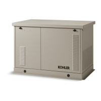
10. Loosen and remove the four controller mounting
screws at the front of the controller. See
Figure 9-2. Remove the controller.
1
tp6196
1. Controller mounting screws (4 ea.)
Figure 9-2 ADC 2100 Mounting Screws
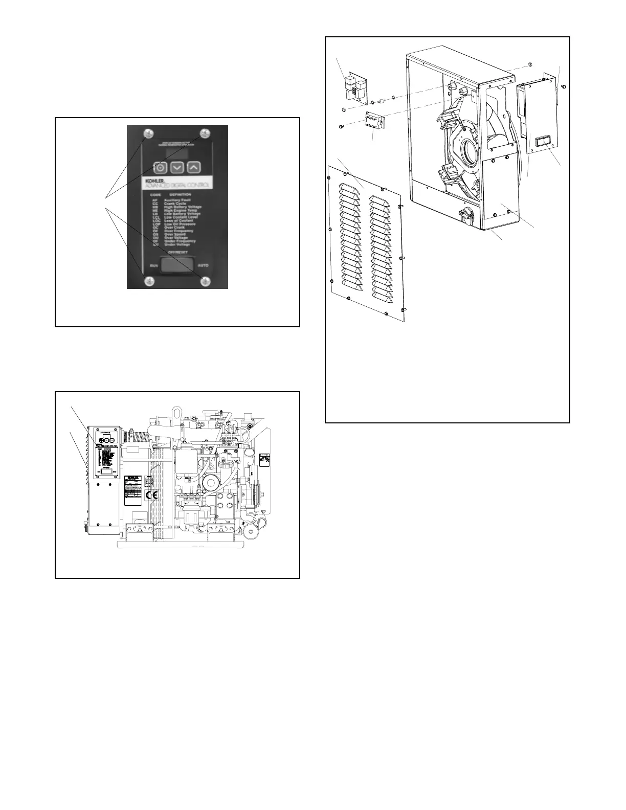
11. Remove the junction box louvered panel. See
Figure 9-3 and Figure 9-4.
1
2
1. ADC 2100
2. Junction box louvered panel
Figure 9-3 Covers
1
1. Junction box louvered panel
2. SCR module
3. Relay board
4. Engine harness-to-controller connection
5. Generator set master switch
6. ADC 2100
7. Line circuit breaker plate
8. Junction box
6
7
8
3
2
5
4
Figure 9-4 Advanced Digital Control (ADC 2100)
12. Remove the junction box, SCR module, and relay
board as necessary. See Figure 9-4.
 Loading...