8.20
Section 8
Electrical System and Components
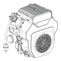
Figure 8-32. Removing Plunger.
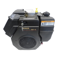
4. Remove the two thru (larger) bolts. See Figure
8-33.
Figure 8-33. Removing Thru Bolts.
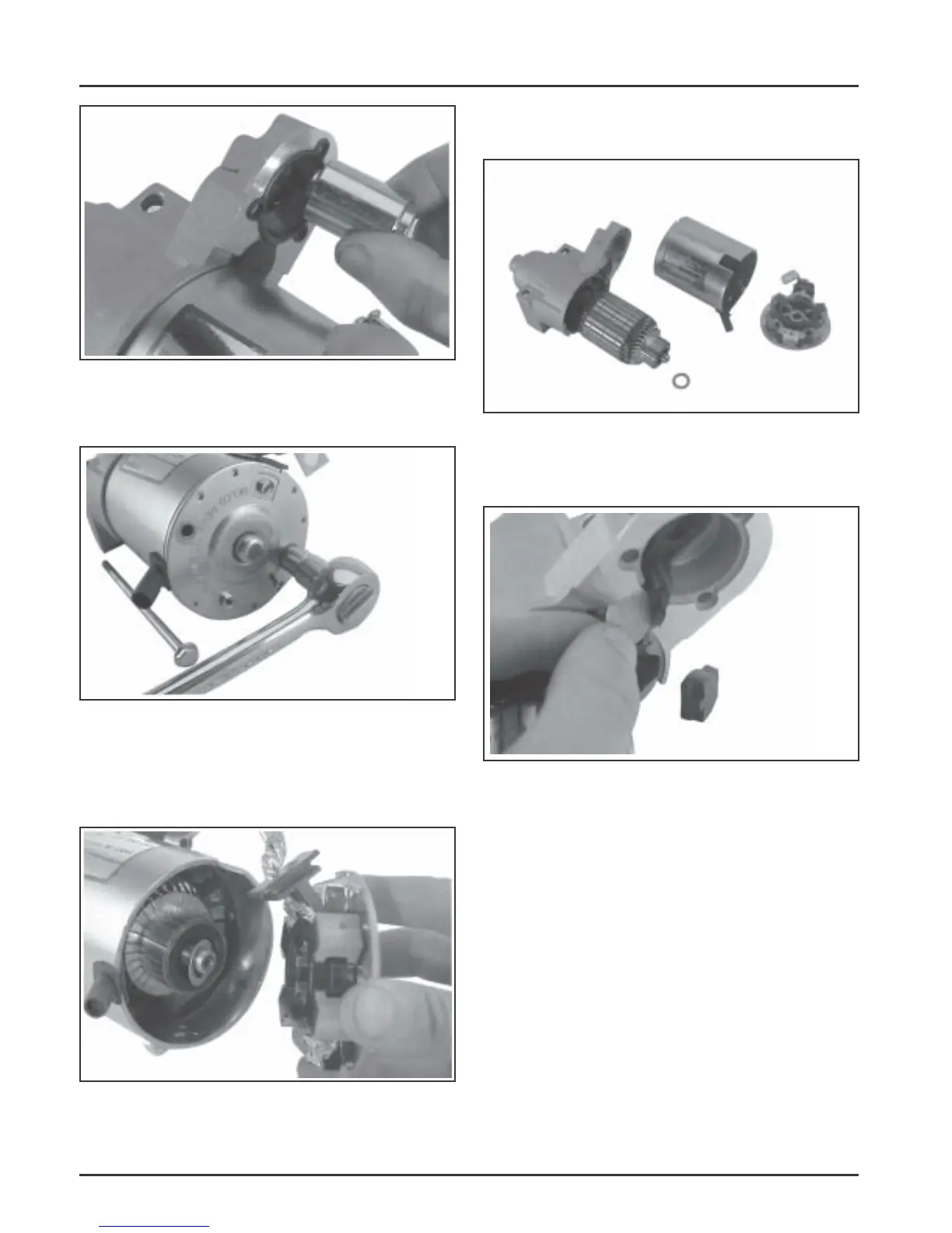
5. Remove the commutator end plate assembly,
containing the brush holder, brushes, springs,
and locking caps. Remove the thrust washer
from inside the commutator end. See Figure 8-34.
Figure 8-34. Removing Commutator End Plate
Assembly.
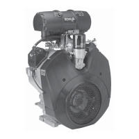
6. Remove the frame from the armature and drive
end cap. See Figure 8-35.
Figure 8-35. Starter Frame Removed.
7. Remove the drive lever pivot bushing and
backing plate from the end cap. See Figure 8-36.
Figure 8-36. Removing Pivot Bushing and Backing
Plate.
8. Take out the drive lever and pull the armature
out from the drive end cap. See Figure 8-37.
9. Remove the thrust washer from the armature
shaft. See Figure 8-37.
 Loading...