eChoke
™
System Standard Checks
A
C
B
D
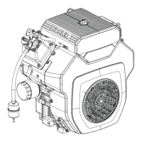
A
Rotary Stepper
Motor 4 Pin
Connector
B Main Wiring Harness
C MIL Test Connector D
2 Pin Connector
Access (Some
Engines)
NOTE: Remove air cleaner system to access carburetor
and eChoke
™
components. Refer to
Disassembly/Inspection and Service and
Reassembly procedure.
Use these procedures and guides to troubleshoot this
system and its components. Perform a system reset
prior to troubleshooting to verify problem still exists. Start
with key switch in OFF position, operate through On-Off -
On sequence and restart engine.
There are standard checks that should be made initially
to help isolate possible problems:
1. Check choke assembly to ensure choke is properly
connected. (Link connected to carburetor and
stepper motor lever.) Removal of air cleaner cover,
element/precleaner, and air cleaner base is required.
2. Make sure link is located and connected properly.
3. Check that choke stepper motor is functioning.
(Operate key switch through On-Off -On sequence to
inspect for any choke movement.) Rotary stepper
motor function can be tested and confi rmed using a
stepper motor controller tool and jumper lead tool.
Refer to Tools and Aids. Testing instructions are
included with these tools.
4. Check that constant power line (RED/GREEN stripe)
connection is connected directly to starter stud.
5. Check for battery voltage (nonoperating), must be
greater than 12.2 VDC open circuit.
(Low battery voltage may prevent proper operation
of stepper motor.)
6. eChoke
™
system is equipped with an MIL connector
that will allow connection of an LED lamp to show
normal eChoke
™
operation or specifi c error codes.
MIL connector is accessible by removing air cleaner
system. This lead (white/red stripe) with a bullet
connector next to stepper motor 4 pin connector
(refer to A and C shown above) to which an LED
(connected to lead and +12 volt power line) can be
connected to review operation or look for error
codes. Once a lamp is connected, operator can
attempt to run through a normal start/crank/run/off
sequence and monitor blink codes to determine if
controller operation is correct.
Both normal operation and error code indication is
listed in blink code table that follows (on next page).
Note that code changes for each level of operation.
7. With air cleaner system removed, connect an LED
test lamp (see Blink Codes for more detail) or use
stepper motor controller tool (see Tools and Aids)
MIL bullet terminal and attach tool battery jump leads
to battery. Refer to instructions in Blink Codes,
Operational Tests, and Failure Modes (on this page
and next page).
8. If no MIL light activity is seen, using a DVOM, attach
black meter lead to battery ground, connect red
meter lead to starter stud, battery voltage should be
seen (must be above 12.2 VDC as in step 3).
9. Locate and carefully slide 2 pin connector through
blower housing air duct and unplug (some engines).
If 2 pin connector is not visible through this duct,
blower housing must be removed to gain access.
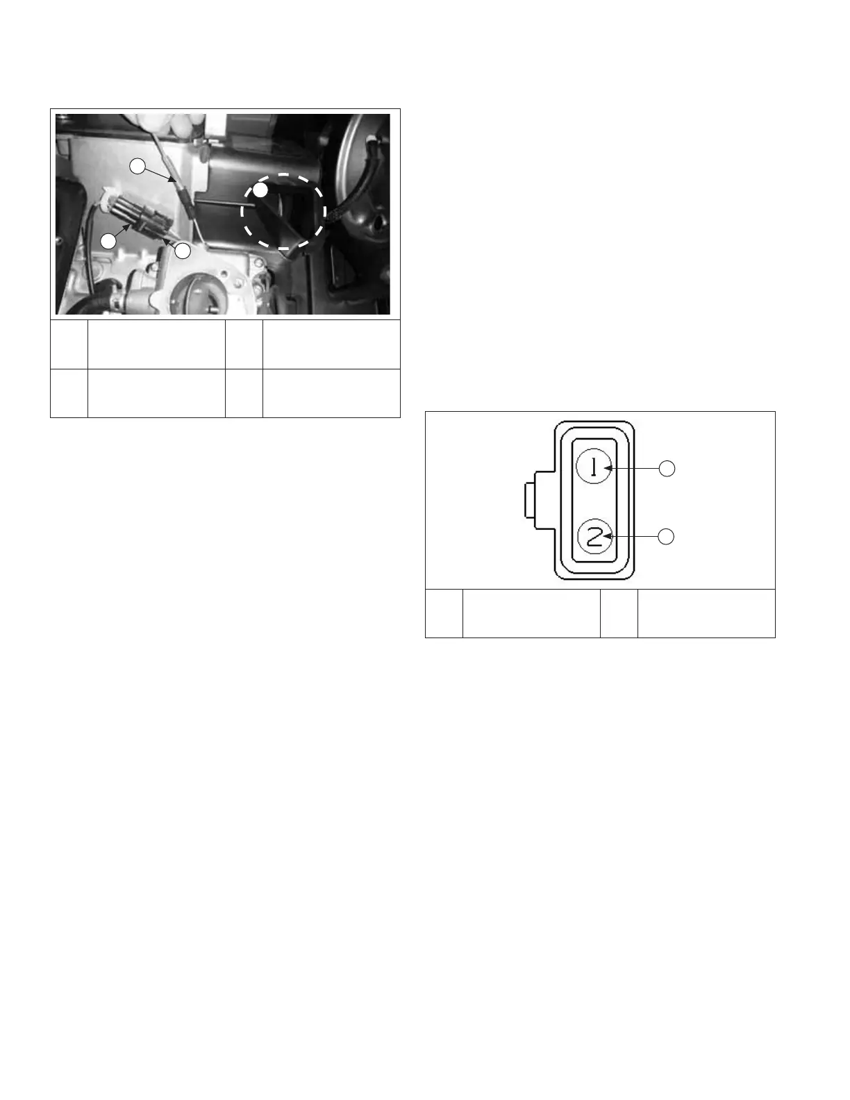
A
B
A
12 Volt Switched
Power Red Wire
B
12 Volt Constant
Power Red/Green
Wire
With key OFF, using red meter lead, probe terminal
2 (red/green wire). Constant power battery voltage
should be seen. If no voltage is seen, cycle key
switch ON and OFF and repeat test. If no voltage is
seen, confi rm harness ground connection. If still no
power, possible fusible link failure has occurred in
harness. Go to step 11 and test for fuse continuity.
10. If voltage is seen in step 9, move red meter lead to
terminal 1. Key OFF, no voltage should be seen.
With meter lead connected to terminal 1, turn key to
ON position. Battery voltage should now be seen.
11. If no power seen in steps 9 and 10, check for
continuity through constant power line (possible
fusible link failure). Disconnect battery; remove red/
green wire eyelet terminal from starter solenoid stud.
Using a DVOM, check for continuity between eyelet
terminal and terminal 2 of 2 pin connector. If no
continuity is found, wiring harness must be replaced.
Fuel System
36 24 690 06 Rev. PKohlerEngines.com