Governor System
42 24 690 06 Rev. PKohlerEngines.com
GCU/Harness Diagnostics and Troubleshooting
NOTE: It is important to use proper sized probes to
perform these tests. Probes that are incorrect
size can damage connector or harness plug.
Ground and Power Tests
1. Switch key to OFF position.
2. Remove GCU and unplug wiring harness.
These two tests check for power and ground supply
to GCU. If either test fails, check if harness, electrical
connections, or electrical system need repair.
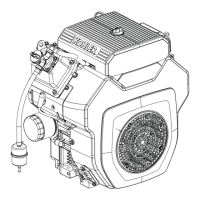
Test 1 Probe Location
A
A Probe Location for Ground Test 1.
Test 1: Identify probe location in connector. Using a
continuity tester, check for a good ground. If ground is
faulty, inspect unit ground, battery ground, connectors,
and wiring harness. Clean or fi x connections or replace
any faulty parts.
If test 1 checks OK, locate probe location in connector,
and check using test 2.
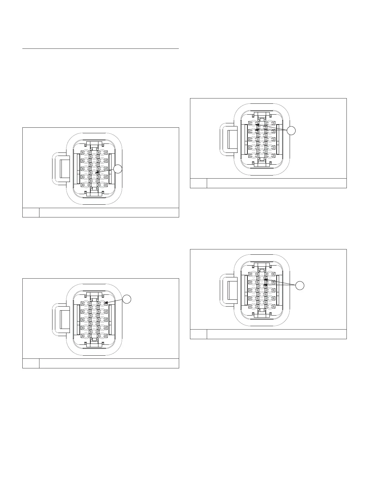
Test 2 Probe Location
A
A Probe Location for Voltage Test 2.
Using a 12 volt meter test for voltage.
On engines equipped with a key switch, turn key switch
to ON position.
Voltage should be within +/- 1 volt of battery voltage. If
voltage is within +/- 1 volt of battery voltage, harness
is OK, replace GCU. If not within +/- 1 volt of battery
voltage, check connections and replace wiring harness if
necessary.
Ohms Tests
1. Remove GCU and unplug wiring harness.
These two tests are for measuring resistance of DLA
circuit that sends a signal to GCU. If either test fails,
DLA is no good and should be replaced. If both tests are
good, DLA is neither shorted or open, it is good. Another
component, connection, or input is most likely at fault.
Test 1 Probe Location
A
A Probe Locations for OHMs Test 1.
Test 1: Identify probe locations in connector. Using a
digital multi-meter set to lowest scale (0-200 ohms),
place probes onto harness making sure of a good
connection. Resistance should be between 47.7 and
58.3 ohms.
If test 1 checks OK, locate wire ends in connector and
check using test 2.
Test 2 Probe Location
A
A Probe Locations for OHMs Test 2.
Test 2: Identify probe locations in connector. Using a
digital multi-meter set to lowest scale (0-200 ohms),
place probes onto harness making sure of a good
connection. Resistance should be between 47.7 and
58.3 ohms.
If either test 1 or 2 fail resistance test, fault could also
be caused by a break/cut in wiring harness. Inspect and
test for a potential harness issue prior to replacing DLA
assembly.