Electrical System
44
62 690 01 Rev. JKohlerEngines.com
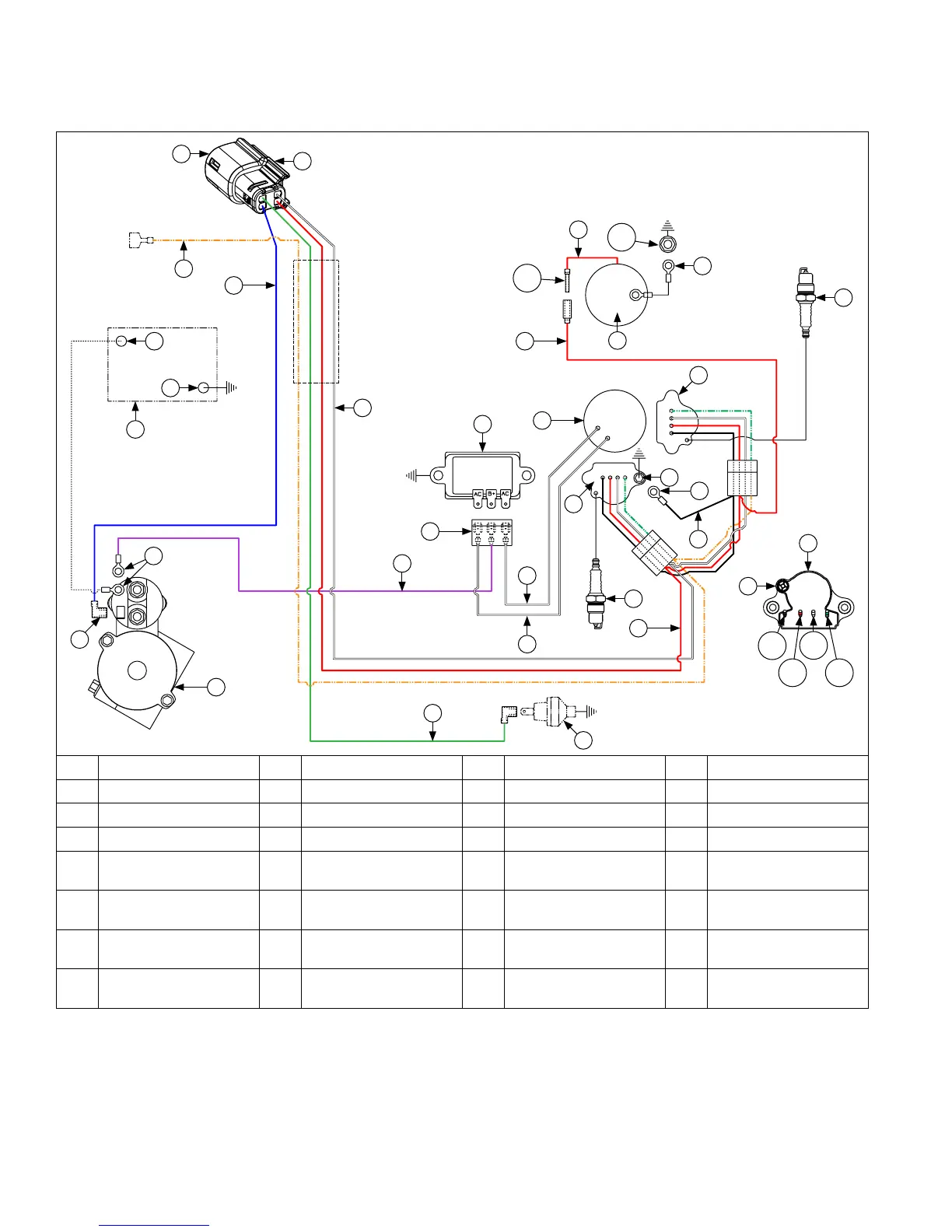
Wire Diagram-15/20/25 Amp Regulated Battery Charging System with DSAI Ignition and Five Pin Connector
(Gasoline/LP-NG Non-Kohler Power Systems Application)
A
B
S
K
F
I
M
L
Z
H
S
X
U
P
Y
G
X
AA
AB AD
AC
D
W
J
T
N
Y
E
T
Q
B
T
C
B
R
V
O
AF
A Blue B Red C Green D Orange
E Violet F White G Black H Connector
I Polarity Ribs J Battery K Battery Positive L Battery Negative
M Starter Solenoid Stud N Starter Solenoid Tang O Starter P Oil Sentry
™
Q Rectier-Regulator R
Rectier-Regulator
Connector
S Spark Plug(s) T Ignition Module(s)
U
Module Mounting
Screw
V
Flywheel Stator
Assembly
W Carburetor X Ground
Y
White
(AC Charging Leads)
Z Spark Plug Lead AA Black (Ground) AB Red (B+)
AC White (Shut Off) AD Green (LP/NG Switch) AE Solenoid Lead AF
Carburetor Mounting
Stud
AE