8.34
Section 8
Electrical System and Components
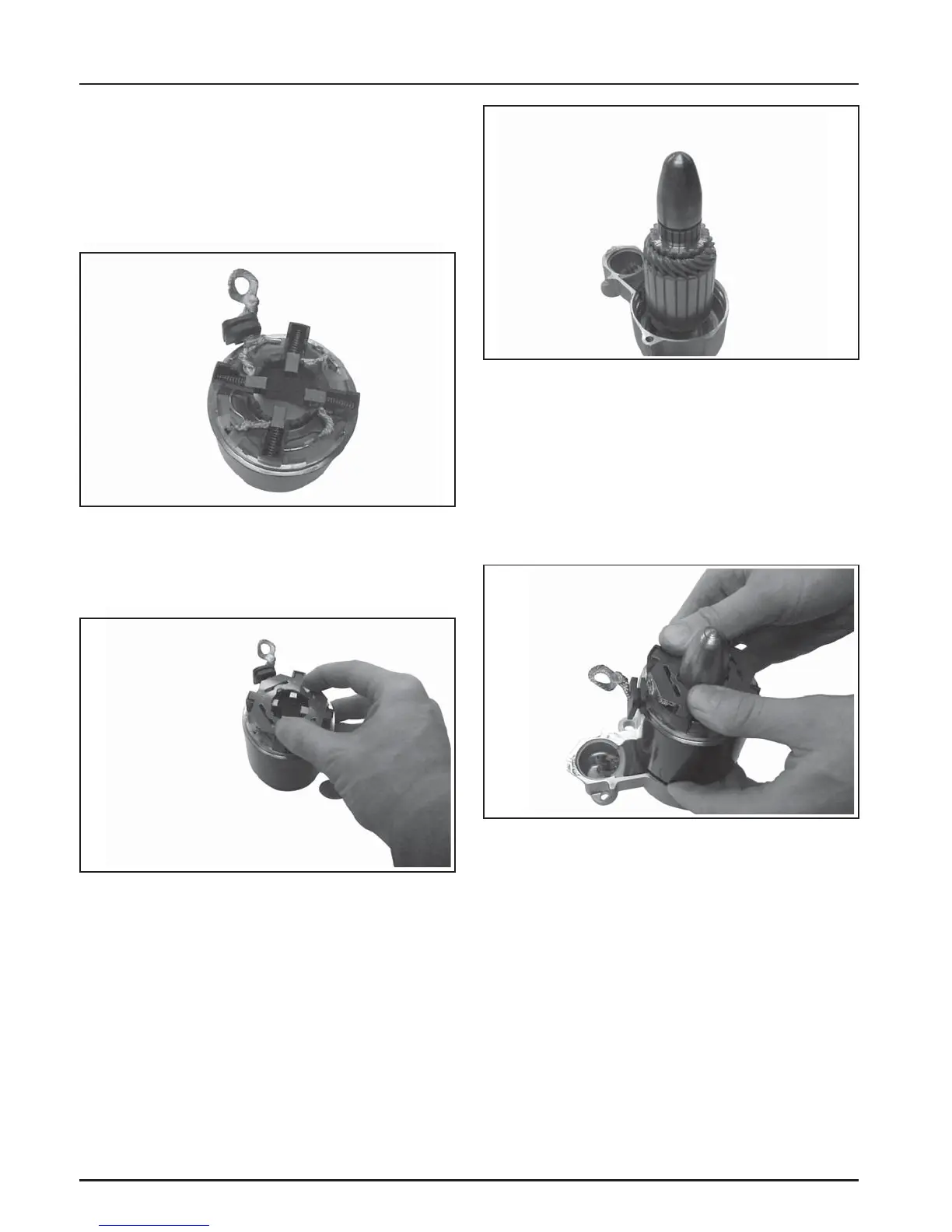
7. Mount the brush holder to rear of starter frame.
Install the four brushes into the corresponding
slots. Then carefully work (set) each of the four
brush springs into position behind the brushes.
Slide the rubber insulating grommet onto the
small corresponding plastic tab on frame. See
Figure 8-64.
Figure 8-64. Mounting Brush Holder to Frame.
8. Position the insulator over the brushes and
springs. Hold it firmly in place so the springs do
not come out. See Figure 8-65.
Figure 8-65. Holding Insulator in Place.
9. Stand the armature/drive end cap assembly on
end so the commutator end is up. Place brush/
armature installation tool over the end of
armature shaft until it rests against the
commutator. See Figure 8-66.
Figure 8-66. Tool on end of Armature.
10. Carefully slide the frame with the brush plate
assembly down over the tool and onto armature
and drive end cap, aligning the cutout with lever
section (on top). The rubber insulating grommet
should also be up. See Figure 8-67.
NOTE: Maintain pressure on the insulator while
installing so the springs do not come out.
Figure 8-67. Installing Frame with Brush Plate
Assembly.
11. Remove the tool and install the commutator end
cap, aligning the cutout with the insulating
grommet. See Figure 8-68.