8.10
Section 8
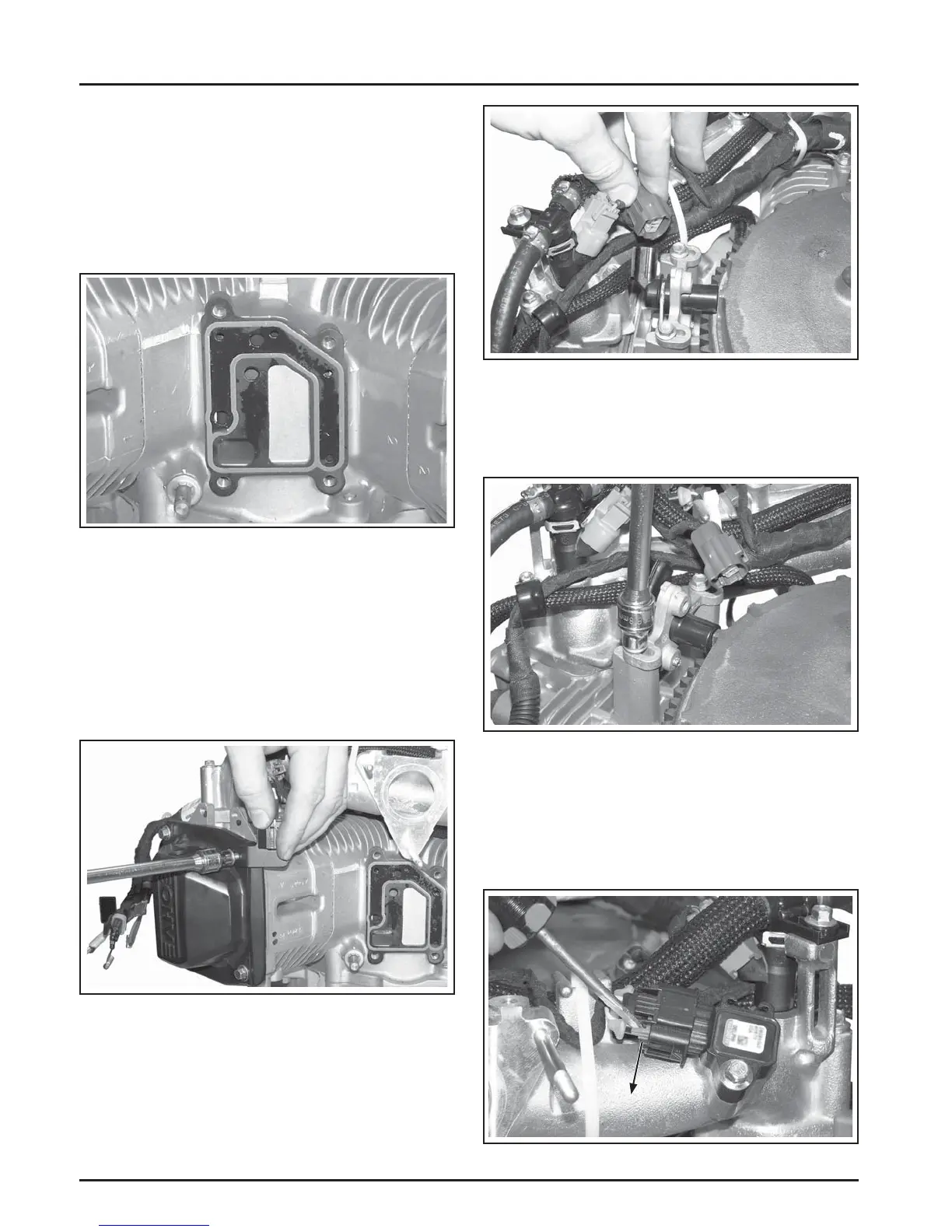
Disassembly
Slide
Locking
Tab
Figure 8-38. Disconnect Crankshaft Position
Sensor.
2. Remove the two hex fl ange screws securing the
cranksha position sensor. See Figure 8-39.
Figure 8-39. Remove the Crankshaft Position
Sensor.
Remove the Manifold Absolute Pressure
(MAP) Sensor
1. With a screwdriver, slide the locking tab on the
electrical connector. See Figure 8-40.
Figure 8-40. Slide Locking Tab on Connector.
5. Pry under the protruding edge of the breather
cover with a screwdriver to break the gasket
seal. See Figure 8-35. Do not pry on the sealing
surfaces as it could cause damage resulting in
leaks.
6. Remove the breather cover and gasket. See Figure
8-36.
Figure 8-36. Removing Breather Cover Gasket.
Remove Valve Covers
1. Remove the four hex fl ange screws securing
each valve cover. Note valve cover diff erences
for proper location in reassembly. Ensure any
brackets removed are reassembled in the same
location. See Figure 8-37.
2. The covers should li off without prying.
Figure 8-37. Removing Valve Cover.
Remove Crankshaft Position Sensor
1. Disconnect the electrical connector to the
cranksha position sensor. See Figure 8-38.