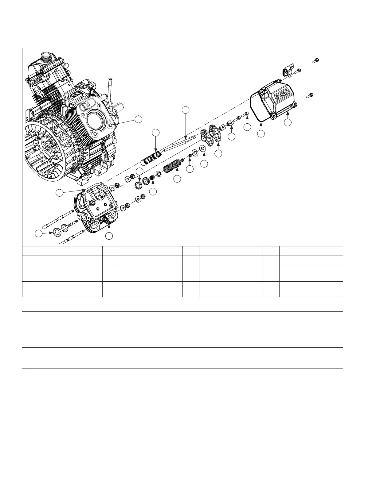
Cylinder Head Components
A
B
C
D
H
I
L
G
F
J
M
K
N
O
P
E
A Valve Cover B Valve Cover Gasket C Hex Flange Screw D Rocker Arm Pivot
E Rocker Arm F Push Rod G Hydraulic Lifter H Valve Cap
I Valve Keeper J Valve Spring K Valve Seal L
Valve Spring
Retainer
M Cylinder Head N
Cylinder Head
Gasket
O Valve P Dowel Pin
Remove Valve Covers
1. Remove screws securing each valve cover. Note valve cover diff erences for proper location in reassembly.
Ensure any brackets and clips/clamps removed are reassembled in same location.
2. Covers should lift off without prying.
Remove Spark Plugs
Remove spark plug from each cylinder head.
Remove Cylinder Heads and Hydraulic Lifters
NOTE: Cylinder heads are retained using either screws or nuts and washers on studs. Do not interchange or mix
components.
1. Remove screws or nuts and washers securing each cylinder head. Discard screws or nuts and washers once
removed. Do not reuse. Studs (if present) should only be removed if damaged or if cylinder reconditioning is
necessary. Once removed, they must be replaced.
2. Mark location of push rods as either intake or exhaust and cylinder 1 or 2. Push rods should always be reinstalled
in same positions.
3. Carefully remove push rods, cylinder heads, and head gaskets.
4. Remove lifters from lifter bores. Use a hydraulic lifter tool. Do not use a magnet to remove lifters. Mark lifters by
location, as either intake or exhaust, and cylinder 1 or 2. Hydraulic lifters should always be reinstalled in same
position.
Disassembly/Inspection and Service
170 24 690 01 Rev. SKohlerEngines.com