EFI SYSTEM-ECH WITHOUT OXYGEN SENSOR
94
24 690 01 Rev. SKohlerEngines.com
WARNING
Explosive Fuel can cause fi res and severe
burns.
Do not fi ll fuel tank while engine is hot or
running.
Gasoline is extremely fl ammable and its vapors can
explode if ignited. Store gasoline only in approved
containers, in well ventilated, unoccupied buildings,
away from sparks or fl ames. Spilled fuel could ignite if it
comes in contact with hot parts or sparks from ignition.
Never use gasoline as a cleaning agent.
NOTE: Engines built from factory without an oxygen
sensor are designed without an oxygen sensor.
No attempt should be made to install one in this
system as it will not function.
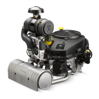
Typical electronic fuel injection (EFI) system and related
components include:
● Fuel pump module and lift pump.
● Fuel fi lter.
● High pressure fuel line.
● Fuel line(s).
● Fuel injectors.
● Throttle body/intake manifold.
● Electronic control unit (ECU).
● Ignition coils.
● Engine temperature sensor.
● Throttle position sensor (TPS).
● Crankshaft position sensor.
● Temperature/manifold absolute pressure (TMAP)
sensor.
● Malfunction indicator light (MIL) - optional.
● Wire harness assembly & affi liated wiring.
FUEL RECOMMENDATIONS
Refer to Maintenance.
FUEL LINE
Low permeation fuel line must be installed on all Kohler
Co. engines to maintain EPA and CARB regulatory
compliance.
OPERATION
NOTE: When performing voltage or continuity tests,
avoid putting excessive pressure on or against
connector pins. Flat pin probes are
recommended for testing to avoid spreading or
bending terminals.
EFI system is designed to provide peak engine
performance with optimum fuel effi ciency and lowest
possible emissions. Ignition and injection functions are
electronically controlled and monitored.
Central component of system is Electronic Control Unit
(ECU) which manages system operation, determining
best combination of fuel mixture and ignition timing for
current operating conditions.
A lift fuel pump is used to move fuel from tank through
an in-line fuel fi lter and fuel line. Fuel is then pumped
to fuel pump module. Fuel pump module regulates
fuel pressure to a system operating pressure of 39 psi.
Fuel is delivered from fuel pump module through high
pressure fuel line into injectors, which inject fuel into
intake ports. ECU controls amount of fuel by varying
length of time that injectors are on. This can range
from 2 to over 12 milliseconds depending on fuel
requirements. Controlled injection of fuel occurs every
other crankshaft revolution, or once for each 4-stroke
cycle. When intake valve opens, air/fuel mixture is drawn
into combustion chamber,compressed, ignited, and
burned.
ECU controls amount of fuel being injected and ignition
timing by monitoring primary sensor signals for engine
temperature, speed (RPM), and throttle position (load).
These primary signals are compared to preprogrammed
maps in ECU computer chip, and ECU adjusts fuel
delivery to match mapped values.
During certain operating periods such as cold starts,
warm up, acceleration, high load, etc., a richer air/fuel
ratio is required and is normal operation.
ECU is brain or central processing computer of entire
EFI system. During operation, sensors continuously
gather data which is relayed through wiring harness
to input circuits within ECU. Signals to ECU include:
ignition (on/off ), crankshaft position and speed (RPM),
throttle position, engine temperature, intake air
temperature, manifold absolute pressure, and battery
voltage.
ECU compares input signals to programmed maps in
its memory to determine appropriate fuel and spark
requirements for immediate operating conditions. ECU
then sends output signals to set injector duration and
ignition timing.
ECU continually performs a diagnostic check of itself,
each of sensors, and system performance. If a fault
is detected, ECU can turn on a Malfunction Indicator
Light (MIL) (if equipped) on equipment control panel,
store fault code in its fault memory, and go into a default
operating mode. Depending on signifi cance or severity
of fault, normal operation may continue. A technician can
access stored fault code using a blink code diagnosis
fl ashed out through MIL. An optional computer software
diagnostic program is also available, see Tools and Aids.
ECU requires a minimum of 6.0 volts to operate.
To prevent engine over-speed and possible failure, a
rev-limiting feature is programmed into ECU. If maximum
RPM limit (4500) is exceeded, ECU suppresses injection
signals, cutting off fuel fl ow. This process repeats itself in
rapid succession, limiting operation to preset maximum.
 Loading...