38
Disassembly/Inspection and Service
KohlerEngines.com 18 690 01 Rev. B
Inspection and Service
After cleaning, check fl atness of cylinder head and
corresponding top surface of crankcase, using a surface
plate or piece of glass and feeler gauge. Maximum
allowable out of fl atness is 0.1 mm (0.0039 in.).
Carefully inspect valve mechanism parts. Inspect valve
springs and related hardware for excessive wear or
distortion. Check valves and valve seats for evidence
of deep pitting, cracks, or distortion. Check running
clearance between valve stems and guides.
Hard starting, or loss of power accompanied by high
fuel consumption may be symptoms of faulty valves.
Although these symptoms could also be attributed to
worn rings, remove and check valves fi rst. After removal,
clean valve heads, faces, and stems with a power wire
brush.
Then, carefully inspect each valve for defects such as
warped head, excessive corrosion, or worn stem end.
Replace valves found to be in bad condition.
Valve Guides
If a valve guide is worn beyond specifi cations, it will not
guide valve in a straight line. This may result in burned
valve faces or seats, loss of compression, and excessive
oil consumption.
To check valve guide-to-valve stem clearance,
thoroughly clean valve guide and, using a split-ball
gauge, measure inside diameter of guide. Then, using
an outside micrometer, measure diameter of valve stem
at several points on stem where it moves in valve guide.
Use largest stem diameter to calculate clearance by
subtracting stem diameter from guide diameter. If intake
or exhaust clearance exceeds specifi cations in Valve
Specifi cation table, determine whether valve stem or
guide is responsible for excessive clearance.
If guides are within limits but valve stems are worn
beyond limits, install new valves.
Valve Seat Inserts
Hardened steel alloy intake and exhaust valve seat
inserts are press-fi tted into cylinder head. Inserts are
not replaceable but can be reconditioned if not too badly
pitted or distorted. If cracked or badly warped, cylinder
head should be replaced.
Recondition valve seat inserts following instructions
provided with valve seat cutter being used. Cutting
proper valve face angle, as specifi ed in Clearance
Specifi cations table and proper valve seat angle (89.5°-
90°) will achieve desired 0° (1° full cut) interference
angle where maximum pressure occurs on outside
diameters of valve face and seat.
Lapping Valves
Reground or new valves must be lapped in, to provide
proper fi t. Use a hand valve grinder with a suction cup
for fi nal lapping. Lightly coat valve face with a fi ne grade
of grinding compound, then rotate valve on seat with
grinder. Continue grinding until a smooth surface is
obtained on seat and on valve face. Thoroughly clean
cylinder head in hot, soapy water to remove all traces of
grinding compound. After drying cylinder head, apply a
light coating of SAE 10 oil to prevent rusting.
Intake Valve Stem Seal
Some engines use a valve stem seal on intake valve.
Always use a new seal when valves are removed
from cylinder head. Seals should also be replaced if
deteriorated or damaged in any way. Never reuse an old
seal.
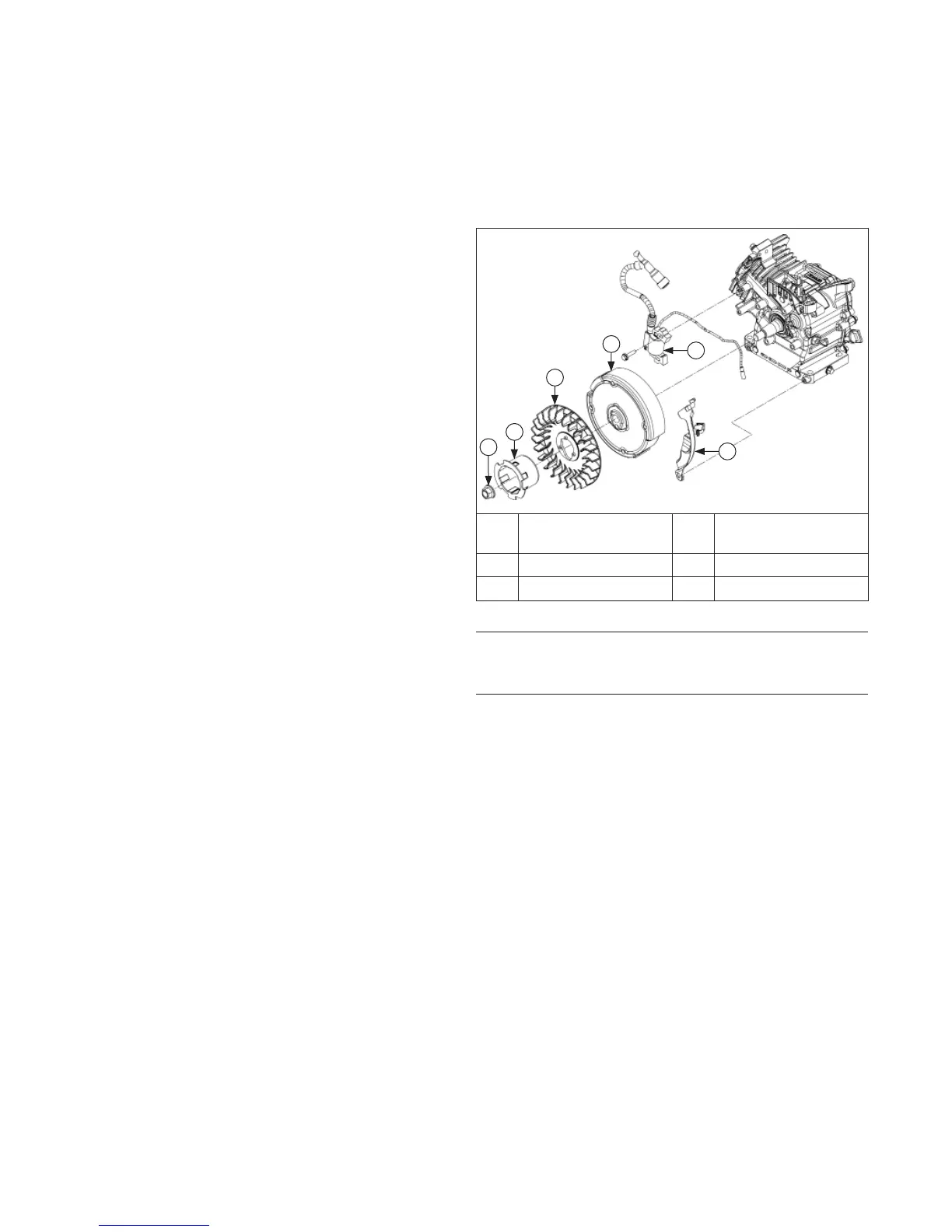
Flywheel/Ignition Components
A
B
C
D
F
E
A
Flywheel Retaining
Nut
B Drive Cup
C Flywheel Fan D Flywheel
E Flywheel Shield F Ignition Module
Remove Ignition Module
Remove screws securing ignition module to crankcase.
Remove module.
Remove Flywheel
NOTE: Whenever possible, an impact wrench should be
used to loosen fl ywheel retaining nut. A fl ywheel
strap wrench may be used to hold fl ywheel when
loosening or tightening fl ywheel retaining nut.
NOTE: Always use a puller to remove fl ywheel from
crankshaft. Do not strike fl ywheel or crankshaft
as these parts could become cracked or
damaged.
1. Remove fl ywheel retaining nut.
2. Remove drive cup and fan from fl ywheel.
3. Remove screw and shield on right side of fl ywheel
(required for use of puller in next step).
4. Remove fl ywheel from crankshaft using a suitable
puller.
5. Remove fl ywheel key from crankshaft keyway.
Inspection
Inspect fl ywheel for cracks and fl ywheel keyway for
damage. Replace fl ywheel if it is cracked. Replace
fl ywheel, crankshaft, and key if fl ywheel key is sheared
or keyway is damaged.

 Loading...