Electrical System
3732 690 01 Rev. G KohlerEngines.com
Digital Spark Advance Module (DSAM) Ignition System
DSAM, previously known as Smart-Spark
™
,
equipped engines utilize an electronic capacitive discharge ignition
system with electronic spark advance. A typical application consists of following components:
● 1 magnet assembly which is permanently affi xed to fl ywheel.
● 2 electronic capacitive discharge ignition modules which mount on engine crankcase.
● 1 spark advance module which mounts to engine shrouding.
● 1 12-volt battery which supplies current to spark advance module.
● 1 kill switch (or key switch) which grounds spark advance module to stop engine.
● 2 spark plugs.
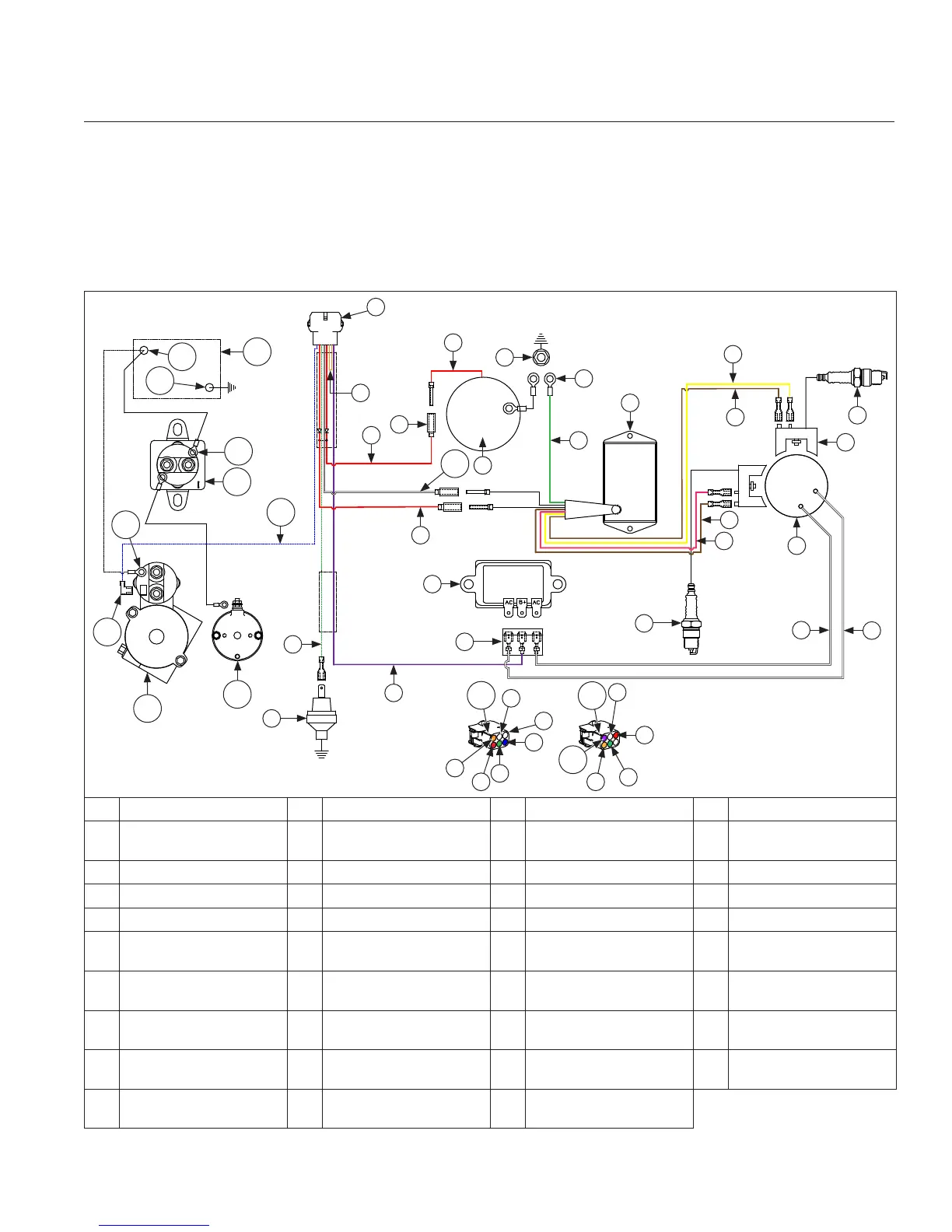
Wiring Diagram-Digital Spark Advance Module (DSAM) Ignition System
W
B
R
Z
A
B
C
E
D
F
F
H
K
G
G
J
Q
O
N
P
Q
S
U
T
B
X
T
B
Q
Y
Y
K
L
M
I
V
AI
AH
AF
AG
AE
AM
AL
AK
AA
AA
AB
AJ
AC
AD
A Oil Sentry™ (Optional) B Green C Violet (Charging) D Rectifi er-Regulator
E
Rectifi er-Regulator
Connector
F Spark Plug(s) G
White
(AC Charging Leads)
H
Flywheel Stator
Assembly
I Ignition Module(s) J Yellow (Trigger) K Brown L Pink (Trigger)
M DSAM N Ground O Intake Manifold Screw P Carburetor
Q Red R Solenoid Lead S Red (DSAM Power) T Orange
U Connector V
Solenoid Shift Starter
Assembly (Optional)
W Red or Blue (shown) X Orange or Red (shown)
Y White Z
Violet or Orange
(shown)
AA Polarity Rib AB
Violet (shown)
or Orange
AC Blue AD
White
(Ignition Kill)
AE Battery AF Battery Positive
AG Battery Negative AH Relay Stud AI
Relay Cranking
(Customer Supplied )
AJ Starter Solenoid Stud
AK Starter Solenoid Tang AL
Solenoid Shift Starter
Assembly (Optional)
AM
Inertia Drive Starter
Assembly
 Loading...