78
Reassembly
KohlerEngines.com 32 690 01 Rev. G
Install Intake Manifold
Torque Sequence
1
2
3
4
NOTE: If wires were disconnected from ignition modules
on engines with DSAM, reattach leads and seal
base of terminal connectors with GE/Novaguard
G661 or equivalent dielectric compound. Beads
should overlap between terminals to form a solid
bridge of compound. Do not put any compound
inside terminals.
1. Install intake manifold using new O-rings, with wiring
harness attached, onto cylinder heads. Slide any
wiring harness clips onto appropriate bolts before
installing. Ground lead for fuel solenoid (if equipped)
should be attached to inner screw on side 2. Using
sequence shown, torque screws in 2 increments,
fi rst to 7.4 N·m (66 in. lb.), then to 9.9 N·m
(88 in. lb.).
2. Connect kill lead to tab terminal on standard ignition
modules.
Install Rectifi er-Regulator (if equipped)
1. Install B+ terminal/lead into center position of
rectifi er-regulator plug so it locks in place, and
connect plug to rectifi er-regulator.
2. Attach rectifi er-regulator to opening in backing plate
from underside, and secure with mounting screws.
Torque screws to 4.0 N·m (35 in. lb.)
Install Inner and Outer Cylinder Baffl es
1. Attach outer cylinder baffl es and secure with M6
screw (lower cylinder location), and M5 screw into
backing plate. Tighten screws as listed following step
2.
2. Attach inner baffl es including any lifting straps to
cylinder head fl anges and to 2 crankcase mounting
bosses. Lift strap should be outside outer baffl e.
Secure with M5 screws. Remaining lower inner
baffl e mounting screws will be installed later.
Torque baffl e mounting screws:
M5 screws: 6.2 N·m (55 in. lb.) into a new cored
hole, or 4.0 N·m (35 in. lb.) into a used hole.
M6 screws: 10.7 N·m (95 in. lb.) into a new cored
hole, or 7.3 N·m (65 in. lb.) into a used hole.
3. Install spark advance module (DSAM) if equipped,
onto outer cylinder baffl e.
Install Carburetor
WARNING
Explosive Fuel can cause fi res and severe
burns.
Do not fi ll fuel tank while engine is hot or
running.
Gasoline is extremely fl ammable and its vapors can
explode if ignited. Store gasoline only in approved
containers, in well ventilated, unoccupied buildings,
away from sparks or fl ames. Spilled fuel could ignite
if it comes in contact with hot parts or sparks from
ignition. Never use gasoline as a cleaning agent.
1. Install a new carburetor gasket. Make sure all holes
align and are open.
2. Install carburetor, throttle linkage and governor lever
as an assembly.
3. If carburetor is equipped with a fuel solenoid,
connect red (power) lead. Attach eyelet terminal of
ground lead to inner top carburetor cover mounting
screw.
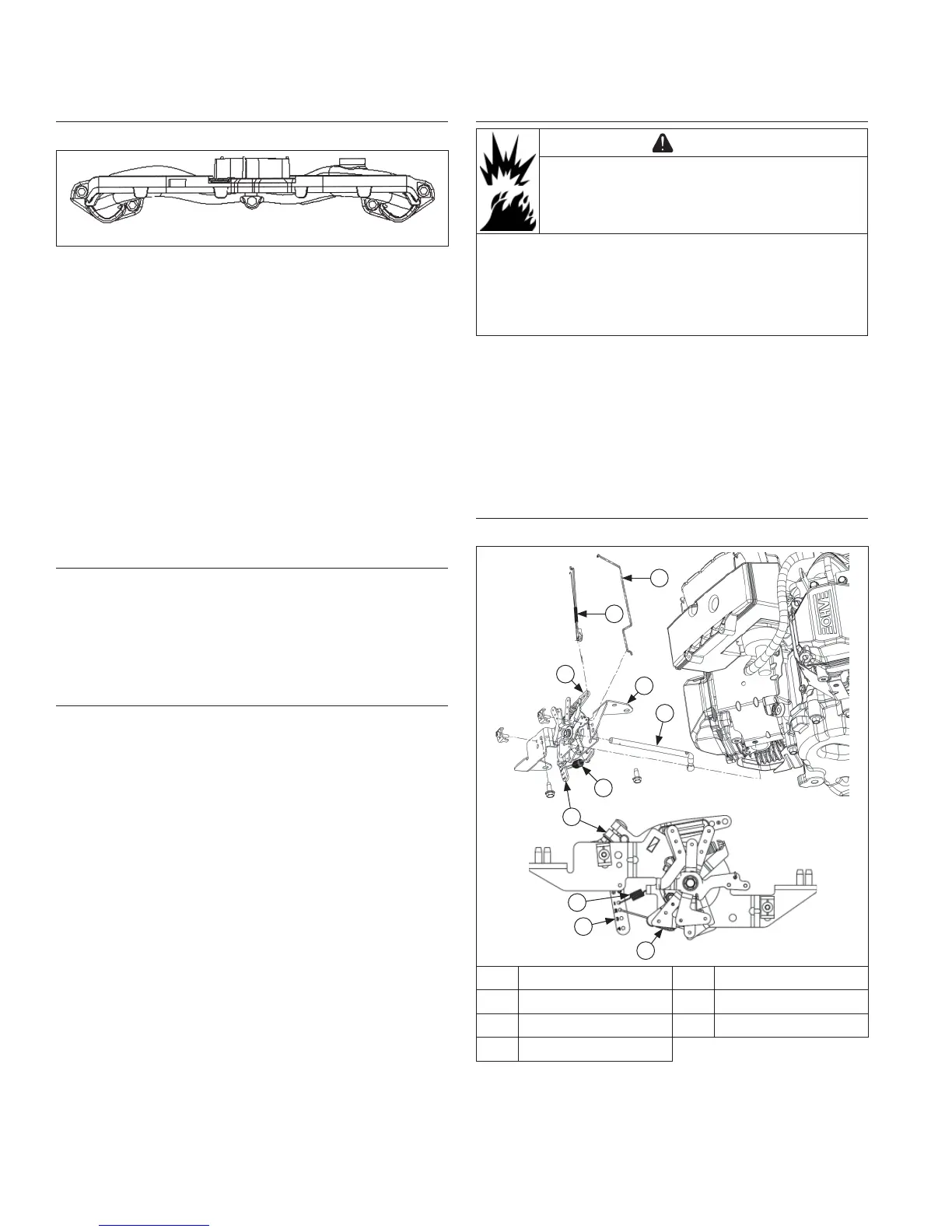
Install External Governor Controls
Control Bracket Components
F
G
C
C
C
B
A
D
D
E
A Choke Linkage B Throttle Linkage
C Governor Lever D Governor Spring
E Cross Shaft F Control Bracket
G Dampener Spring
 Loading...