127Section 8 Component Testing and AdjustmentTP-6356 4/12
8.6 Controller Selector Switch
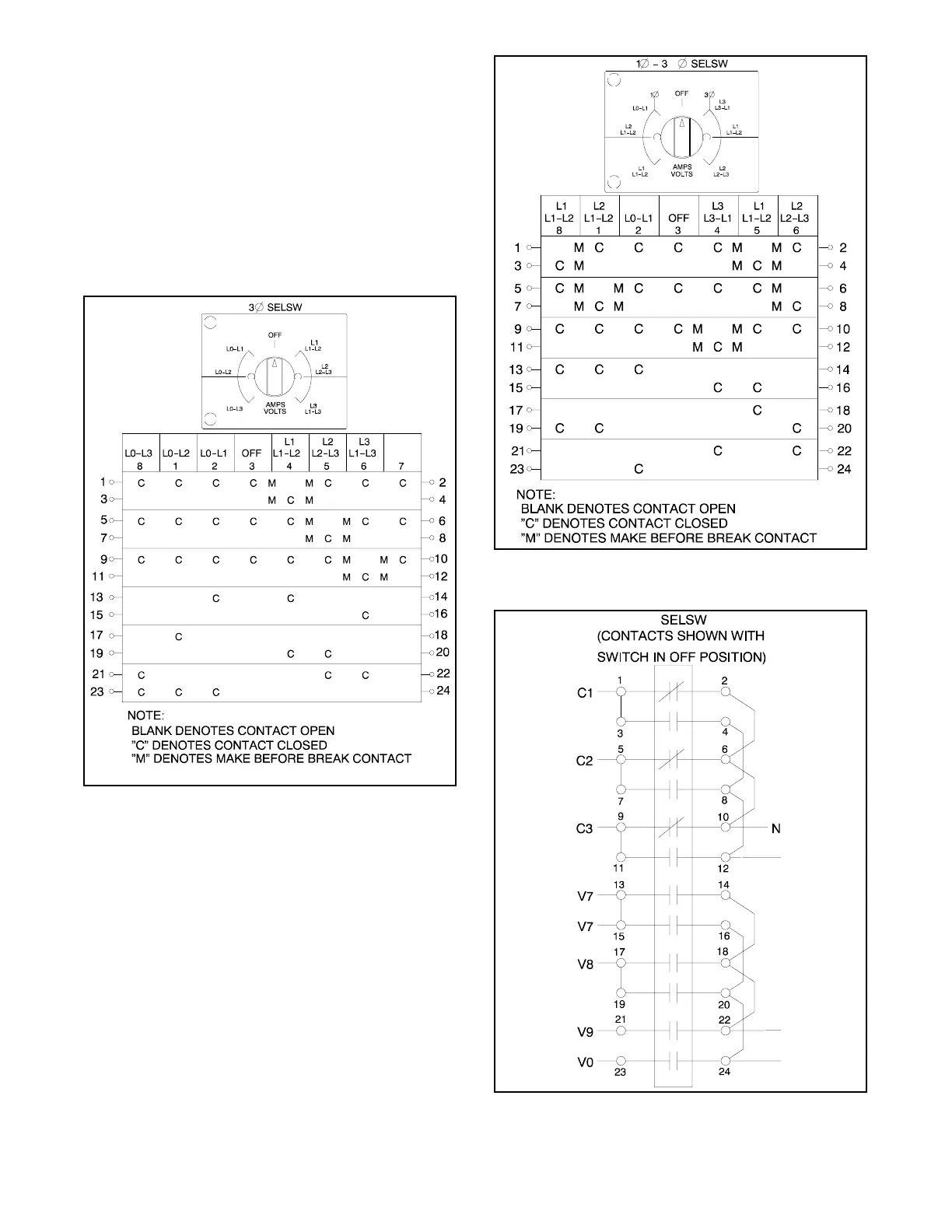
(Decision-Makerr 1 and 3+ Controllers)
The illustrations in Figure 8-4 and Figure 8-5 represent
the electrical connections made to the controller
selector switch. Use this information to troubleshoot the
selector switch when the wiring and/or the selector
switch contacts are in question.
See Figure 8-6 for typical controller selector switch
external connections. See the respective wiring
diagram for actual connections.
ADV-6670A-B
Figure 8-4 Controller Selector Switch, 3-Phase
ADV-6670A-B
Figure 8-5 Controller Selector Switch,
Single-Phase/3-Phase
ADV-6670A-B
Figure 8-6 Controller Selector Switch External
Connections, Typical