7
103
_07
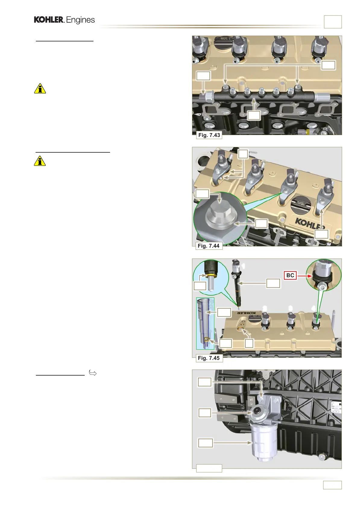
Fig. 7.43
AC
AB
AD
Fig. 7.44
AE
Fig. 7.45
AL
AM
X
Fig. 7.46
1
2 3 4
AN
AP
AW
AF
AG
X
BC
AH
AL
ED0053029590
INFORMATION FOR DISASSEMBLY
7.10.4 Common rail
1 - Undo the screws AB and remove the Common Rail AC.
NOTE: Take care to protect te sensor AD f r o m k n o c k s , m o i s t u r e
and any high temperature source. The internal parts of
the rail cannot be repaired.
Important
• Seal all injection component unions as illustrated in
Para 2.9.8.
• Il Common Rail non è riparabile.
7.10.5 Electronic injectors
Important
• In the event that the electronic injectors are disassembled (not
necessarily replaced), mark them with the relevant cylinder
number from which they originate so as not to confuse them
during re-assembly (Fig. 7.45).
• The electronic injectors cannot be repaired.
• If one or more electronic injectors are to be replaced, the new
calibration data must be inserted in the ECU via a specific
instrument (ST_01).
• Be careful not to damage the gaskets X.
1 -
Undo capscrews AE and remove them together with the
relative washers AF and then brace AG.
2 -
Pull out the electronic injector AH.
NOTE: Should you be unable to remove the electronic injector
(acting only on point BC), use an open-ended spanner
(Ã 34 mm), by applying small rotations to unblock the
component.
3 -
Seal all injection component unions as illustrated in
Par. 2.9.8.
4 -
Ensure that gasket AL has remained in the correct position
(Fig. 7.45).
Otherwise, recover the gasket from inside the electronic
injector AM.
7.10.6 Fuel lter ( )
1 - Undo the fuel cartridge AW from support AP.
2 - Undo the screws AN and remove the filter support AP.

 Loading...


