119
8
_07
Fig. 8.5
X1
Fig. 8.6
S
K1W1
Z1
K
W
R
X
Z
Q
ED0053029590
INFORMATION ABOUT OVERHAULING
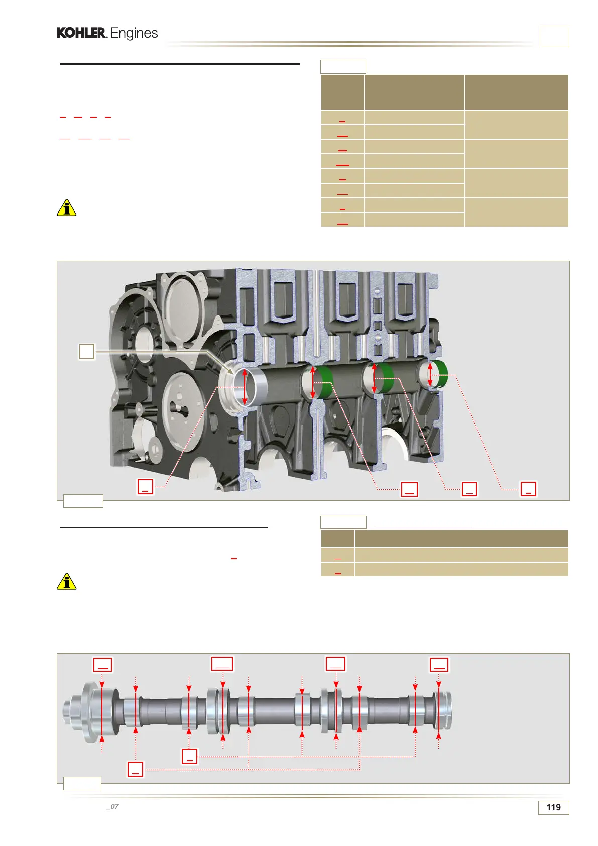
8.2.5 Camshaft housing check for 3 cylinder engine
The camshaft housings only contain the timing system side
bushing Q.
Use an internal dial gauge to measure the diameters of housings
X - W - K - Z.
Use an internal dial gauge to measure the diameters of housings
X1 - W1 - K1 - Z1 (Fig. 8.5).
According to the values measured, calculate the clearance
between the housing and gudgeon, which is to observe the
values in Tab. 8.3a.
The MAX value of wear allowed is 0.120 mm.
Important
• Tab. 8.3a details the dimensional values of new components
only.
REF. DIMENSIONS (mm)
CLEARANCE VALUE
(mm)
X 44.000 - 44.025
0.040 - 0.085
X1 43.940 - 43.960
W 43.000 - 43.025
0.060 - 0.105
W1 42.920 - 42.940
K 42.000 - 42.025
0.060 - 0.105
K1 41.920 - 41.940
Z 36.000 - 36.025
0.060 - 0.105
Z1 35.920 - 35.940
8.2.6 Camshaft control for 3 cylinder engine
With a micrometer, measure the maximum dimensions of
intake camshaft R and exhaust camshaft S (Tab. 8.3b).
The MAX value of wear allowed is 0.1 mm.
Important
• Tab. 8.3b details the dimensional values of new components
only.
Tab. 8.3a
Housing and camshaft gudgeon dimensions.
REF. DIMENSIONS (mm)
R 32.834 - 32.896
S 33.335 - 33.397
Tab. 8.3b
Camshaft dimensions

 Loading...


