44
2
_07
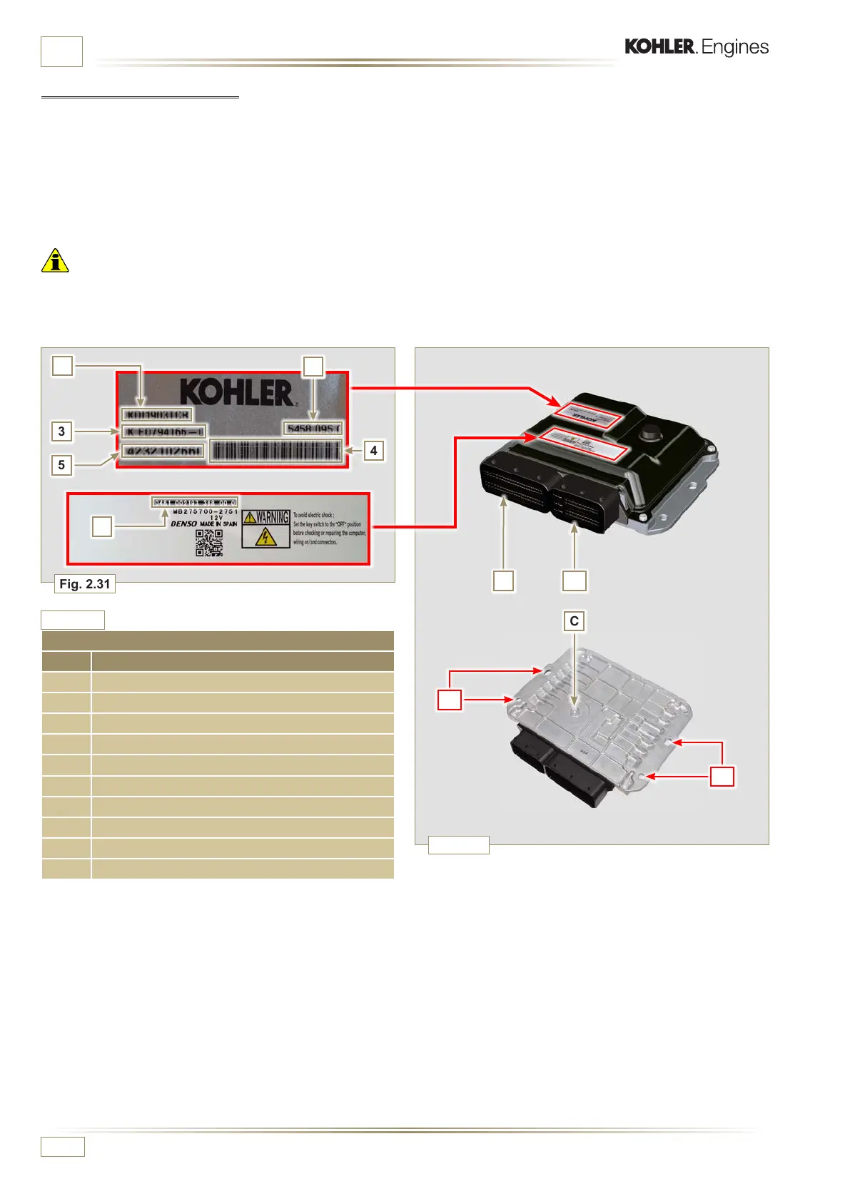
Fig. 2.31
Fig. 2.32
1
2
C
BA
D
D
3
5
4
6
ED0053029590
TECHNICAL INFORMATION
ECU AND ENGINE IDENTIFICATION PLATES
POS. DESCRIPTION
1 Engine model
2 Validation code
3 Engine specications
4 Bar Code of the engine chassis number
5 Engine chassis number
6 ECU identication code
A Connector A (ECU A)
B Connector B (ECU B)
C Barometric capsule
D Fastening points
Tab. 2.33
2.13.2 Control unit (ECU)
E.C.U. CONTROL UNIT (Electronic control unit)
The ECU is a central processor, which monitors and controls
engine operation.
The electronic control unit is responsible for engine
management.
It is tted on the frame of the vehicle, or in the cab (refer to
the technical documentation of the vehicle).
Important
• The ECU must only be used with the configuration defined
by KOHLER, for each individual engine.
2.13.2.1 Installation rules
• Protection degree: 1P 6K/9K.
• Operating temperature: -40°C - +100°C.
• Storage temperature: -40°C - +100°C.
• Do NOT install the ECU on the engine. It should be mounted
on the frame of the vehicle / plant in a position where it will be
well cooled, mechanically protected, and free from vibration
and ingress of moisture.
• It is crucial that the ECU is earthed. Electrical connection
may be as follows: by means of four fixing points
D of the ECU to the vehicle brace, thus ensuring
good connection (avoid painted or insulated parts).
Alternatively, connect using a cable (with 4mm2 section and
a maximum length of 300 mm) from one of the ECU fixing
points D to a plate of mass, taking care to ensure perfect
electrical contact.
• Do NOT mount or replace the control unit with that of another
engine.
• Although externally each ECU seems to be identical,
internally they are specifically configured only for use on the
engine that they are supplied with.
• The control units are not interchangeable nor modifiable.
• Each control unit is accompanied by its adhesive
identification plate.
• The position of the ECU in an application must be done
carefully to protect barometric capsule C from liquids (during
engine washing or engine/vehicle maintenance).
• The connection area (ECU connectors A-B) must not be the
lowest point of all the wiring to prevent any water infiltrations
in the wiring itself.

 Loading...


