6
71
_07
Fig. 6.3
E
F
Fig. 6.2
C
G
Fig. 6.1
ED0053029590
INFORMATION FOR REPLACING THE FUNCTIONAL UNITS
Important
• Before proceeding with operation, carefully read Par. 3.3.2
• In the event of the electronic injectors being disassembled (not
necessarily replaced) their position with respect to individual
cylinders must not be changed when re-assembled. Refer to
the reference between each injector and respective cylinder
number.
• Seal all injection component unions as illustrated in P a r. 2 . 9. 8
during disassembly.
• Handle the components as described in Par. 2.18.
• The high pressure pipes must be replaced every time they
are disassembled.
• After disassembly, protect the sensor against shocks,
dampness and any high temperature sources.
• Replace all seal gaskets after each assembly for all
components on which they are provided.
NOTE: In the event of a leak upon replacement (oil - coolant
- fuel - air), do not intervene with the engine running,
but stop it and wait for 5/10 minutes before checking
and solving the problem.
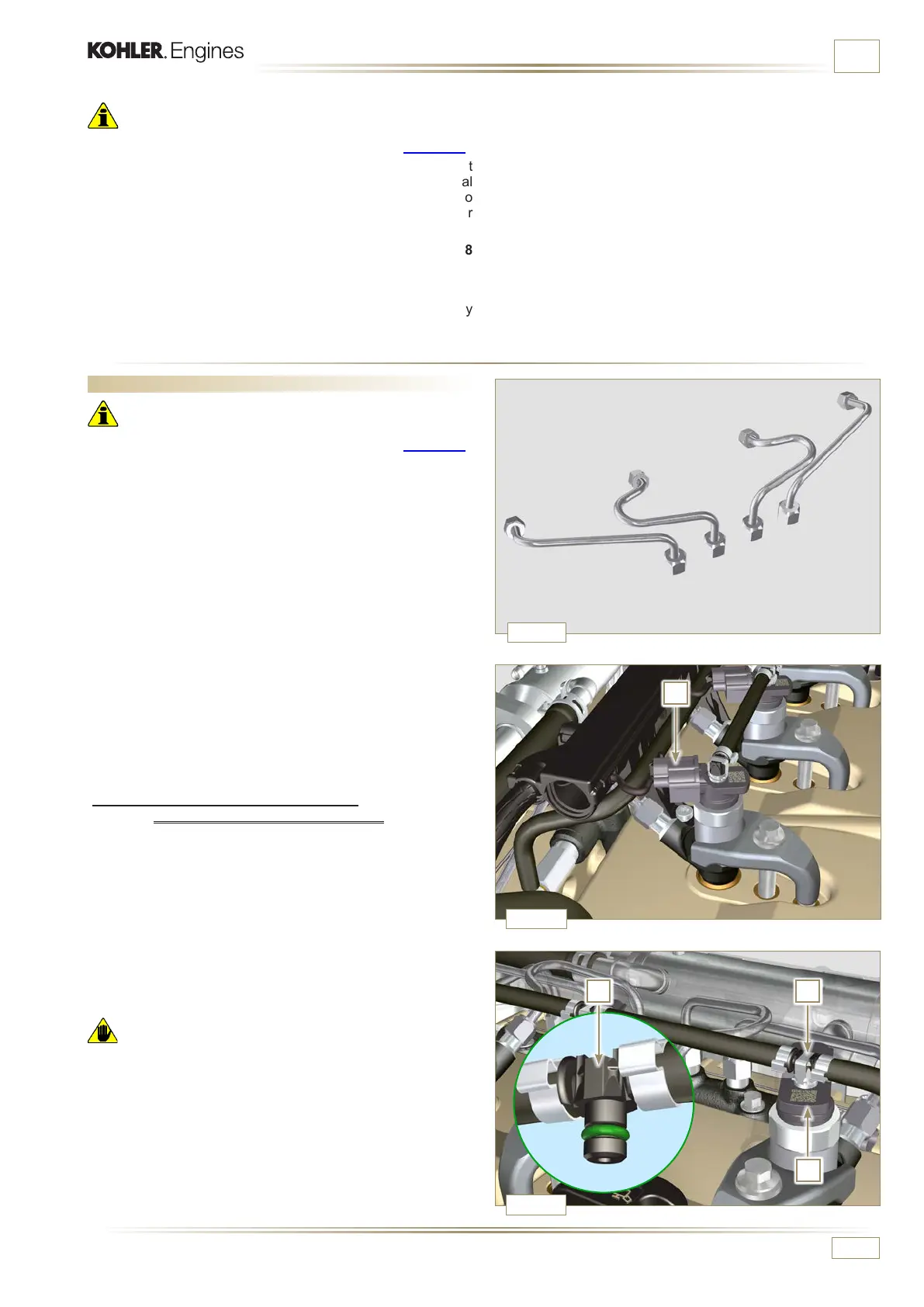
6.1.1 Fuel return pipes disassembly
(Common Rail/electronic injectors)
1 - Disconnect the connector C.
2 -
Remove clips E from the electronic injector F.
3 - Disconnect the junction G from the electronic injector F.
Warning
• After removing the fittings, the clips E must automatically
return to their initial position; otherwise they must be replaced.
4 - Seal all injection component unions as illustrated in
Par. 2.9.8.
6.1 Electronic injector replacement
Important
• Before proceeding with operation, carefully read Par. 3.3.2.
• Always replace the high pressure pipes after each
disassembly.
• Before disassembling the electronic injectors, make sure the
new high pressure pipes are available.
• If a new (or different) electronic injector is fitted on the engine,
the new calibration data must be entered in the ECU via a
specific instrument (ST_01).
• Electronic injectors are not repairable.
• This procedure may be performed on one or more electronic
injectors.

 Loading...


