6
72
_07
M NF
L
Fig. 6.4
1
2
3
4
H
Fig. 6.6
S
Fig. 6.5
P
F
Q
R
F
T
S
Fig. 6.7
AA
F
S
2
3
4
1
X
AB
BC
ED0053029590
INFORMATION FOR REPLACING THE FUNCTIONAL UNITS
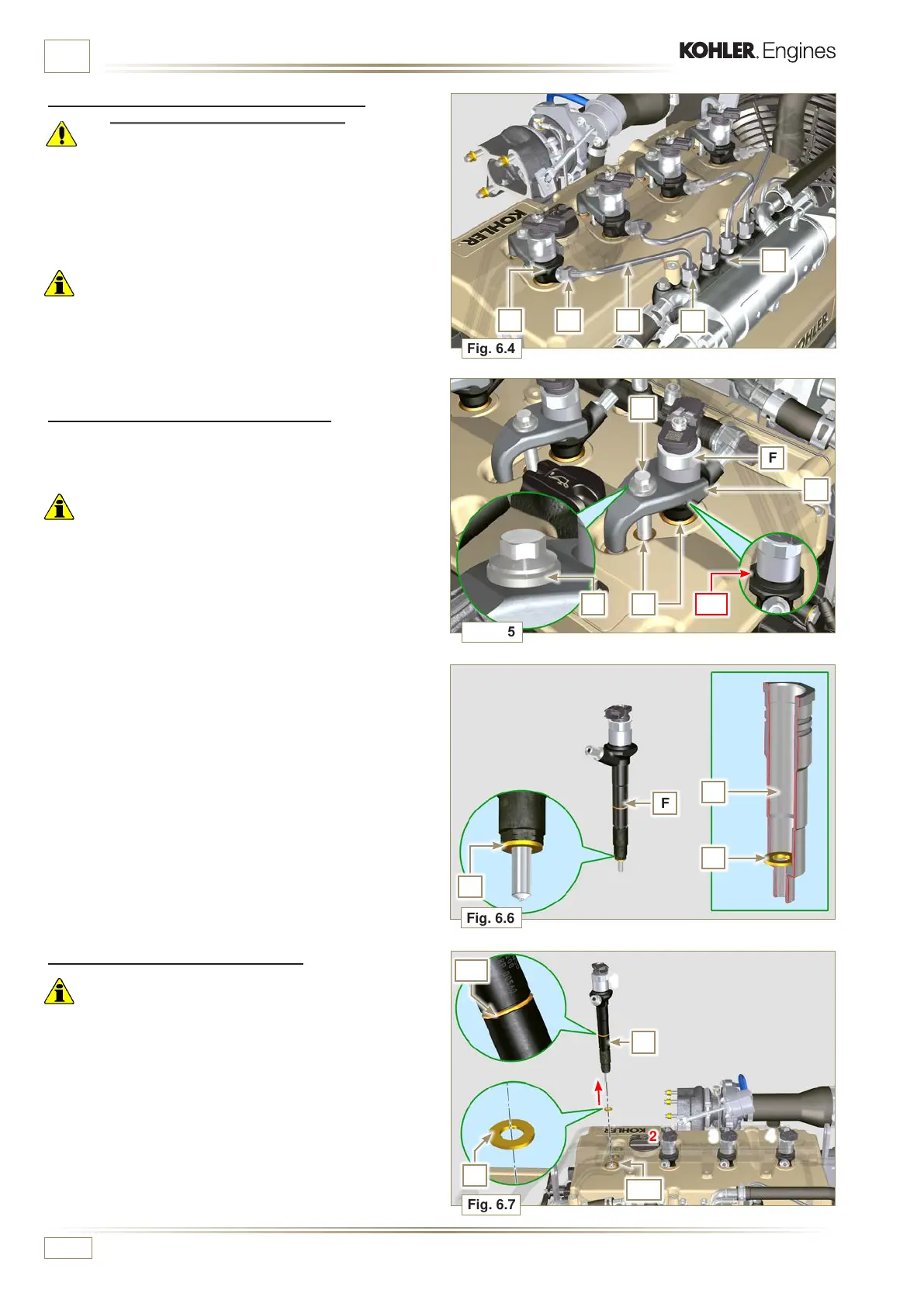
6.1.2 High pressure fuel pipes disassembly
(Common Rail/electronic injectors)
Danger
• The fuel injection circuit is under high pressure, use safety
protections as described in Par 3.4.3.
• Ensure that the Common Rail is not under pressure by slowly
and carefully unscrewing one of the nuts H.
1 -
Undo the nut H on the Common Rail L and then the nut M
on the electronic injector F and remove the pipe N.
Important
• In the event that the electronic injectors are disassembled (not
necessarily replaced), mark them with the relevant cylinder
number from which they originate so as not to confuse them
during re-assembly.
• Seal all injection component unions as illustrated in P a r. 2 . 9 . 8 .
6.1.3 Electronic injectors disassembly
1 - Undo and remove capscrew P with washer R and then
brace Q.
Important
• Be careful not to damage the gaskets X.
• Replace rings X, if damaged.
2 - Pull out the electronic injector F.
NOTE: Should you be unable to remove the electronic injector
(acting only on point BC), use an open-ended spanner
(Ã 34 mm), by applying small rotations to unblock the
component.
3 -
Seal all injection component unions as illustrated in Par.
2.9.8.
4 -
Ensure that gasket S has remained in the correct position
(Fig. 6.6). Otherwise, recover the gasket from inside the
electronic injector T manifold.
6.1.4 Electronic injector assembly
Important
• Always replace and lubricate the gaskets AA and S of the
electronic injectors F with fuel, every time they are replaced.
• Reposition the electronic injectors (not replaced) by following
the references made for disassembly, as indicated in
Par. 6.1.2.
1 -
Insert the gasket S on the electronic injectors F (Fig. 6.7).
2 -
Insert electronic injector F into manifold T, being extra
careful not to damage gasket AB and direct it as indicated
in Fig. 6.7.

 Loading...


