6
73
_07
P
Q
R
AD
Fig. 6.9
Fig. 6.8
N HM L
F
Fig. 6.10
G
AE
Fig. 6.11
F
C
AF
G
E
CLICK
S
ED0053029590
INFORMATION FOR REPLACING THE FUNCTIONAL UNITS
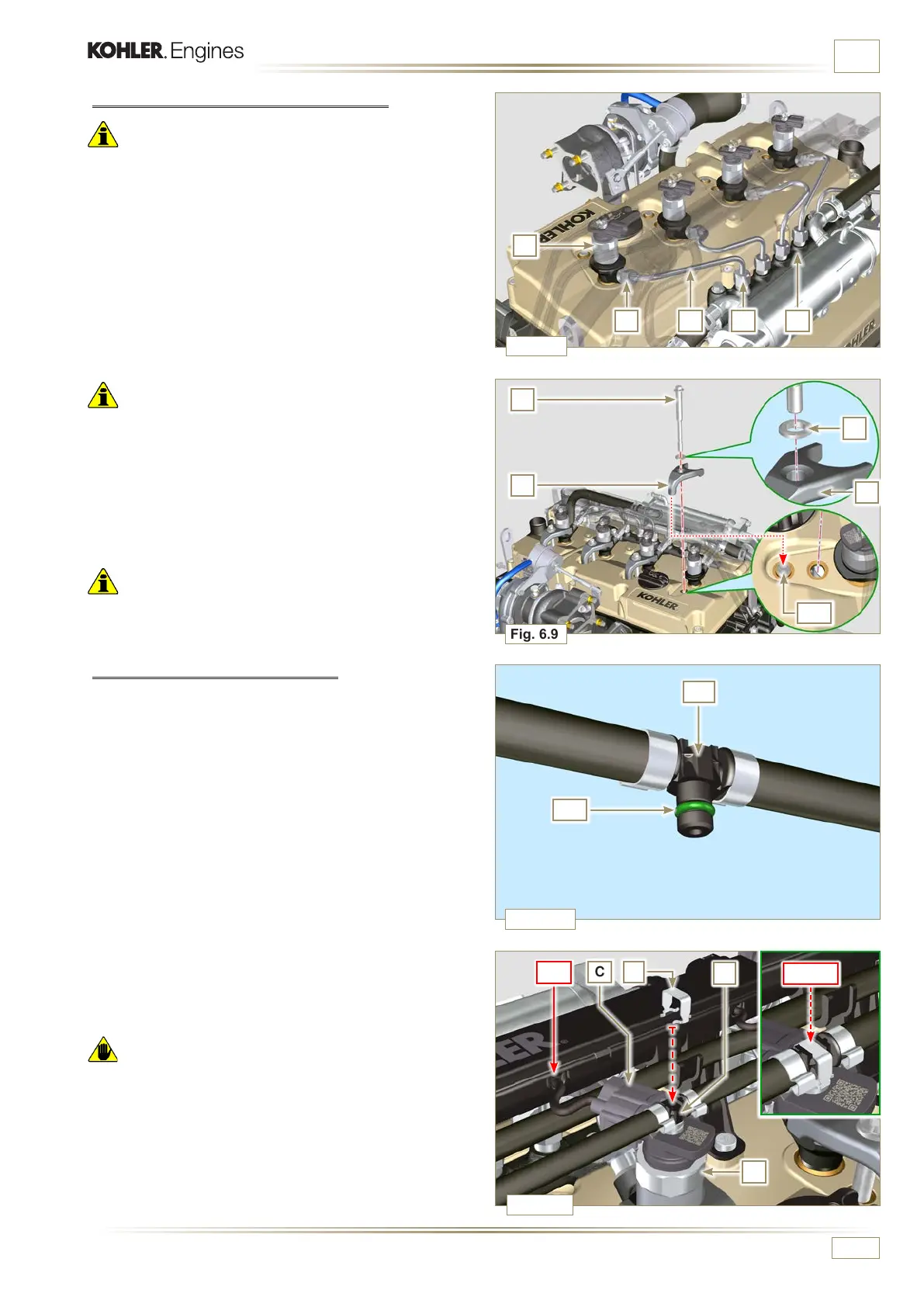
6.1.5 High pressure fuel pipes assembly
Important
• Always replace the pipes N after each assembly.
1 -
Position tube N in the Common Rail seat of the electronic
injector; correct the position of the electronic injector by
means of the entrance of the electronic injector unions F
and Common Rail L.
2 - Apply the nuts H and M by hand without tightening them.
3 -
Position the fastening brace of electronic injectors Q on
capscrew surface AD, insert capscrews P in brace Q
inserting washer R.
Important
• Ensure that brace S is perfectly positioned onto the electronic
injector.
4 - Tighten the fixing screws P of the electronic injector
bracket (tightening torque at 20 Nm).
5 - Tighten the nut M (tightening torque at 25 Nm).
6 - Tighten the nut H (tightening torque at 30 Nm).
Important
• Replace the pipes N (Fig. 6.8) if the screws P are stiff when
tightened.
6.1.6 Fuel return pipes assembly
1 - Check the condition of the gaskets AE.
2 - Insert unions AF onto electronic injectors F and block them
with clips E.
3 - Mount the connectors C on the electronic injectors F.
Warning
• Slightly move the wiring support to check that there is no
voltage in the electrical wire of connector C in correspondence
with the outlet hole A F.

 Loading...


