6
79
_07
Fig. 6.34
B
C A
L
A
A N
B
Fig. 6.32
D
E
R
T
S
C
Fig. 6.33
C DB
Fig. 6.35
L
E
ED0053029590
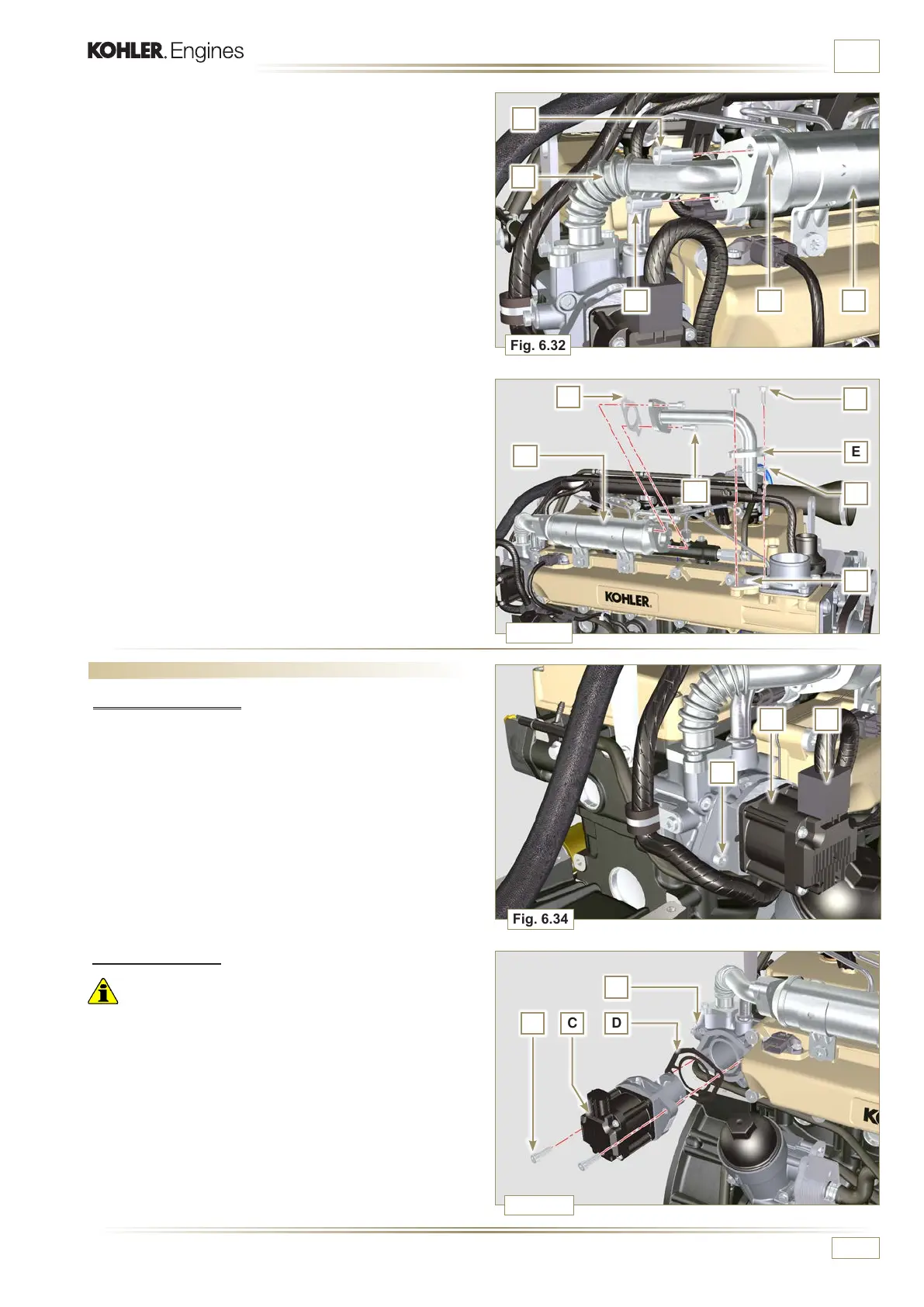
INFORMATION FOR REPLACING THE FUNCTIONAL UNITS
6.4 EGR valve replacement
6.4.1 Disassembly
NOTE: Perform the operations described in Par. 5.1.
1 - Disconnect the connector A from the valve C.
2 - Undo the screws B and remove the EGR valve C with the
relevant gasket.
6.4.2 Assembly
Important
• Always replace gasket D after each assembly.
• The EGR valve is not a serviceable item, and if faulty / worn
out, should be replaced with a new one.
1 - Mount the new gasket D on the valve C.
2 - Fit the valve C on the flange E with screws B (tightening
torque at
10 Nm).
5
- Insert the gasket N between the hose B and the EGR
Cooler L and fix the screws A (tightening torque at
25 Nm)
6
- Insert the hose E in its housing on the manifold S inserting
the gasket R.
7 - Insert the gasket T between the hose E and the EGR
Cooler L and fit the screws C (tightening torque at
25 Nm).
8 - Fit the screws D (tightening torque at 22 Nm - ST_05).
NOTE: Perform the operations described in Par. 10.2.

 Loading...


