140 TP-6694 6/22
6.1.6 Two-Input/Five-Output Module
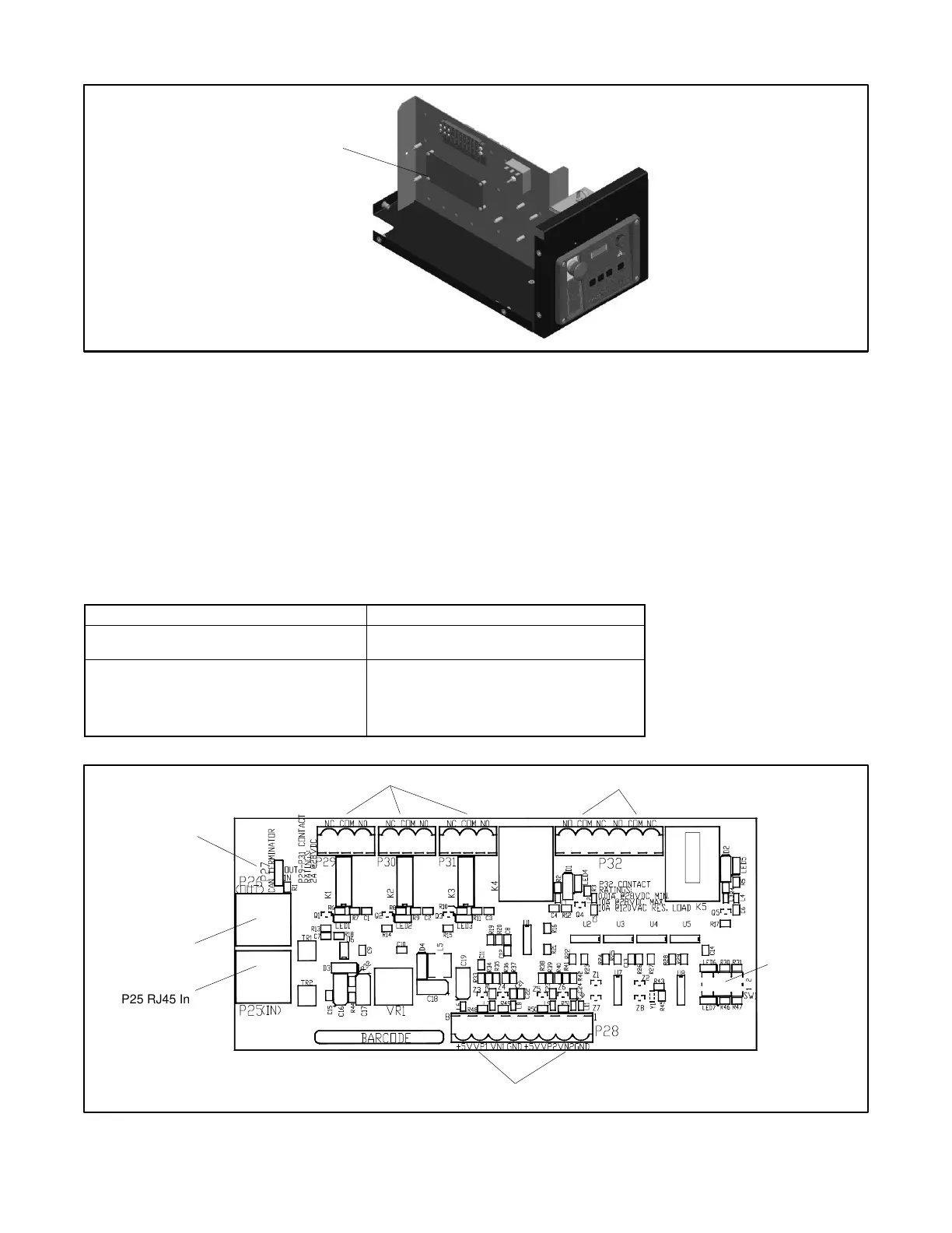
Figure 71 Two-Input/Five-Output Module Location
The two-input/five-output module provides a generator set mounted panel with two analog or digital inputs and five digital outputs.
See Figure 73 for circuit board components and electrical connections to the controller.
See Figure 74 for connections of analog inputs.
See the following subsection, Accessory Connections, for terminal identification.
Use a computer with Kohler SiteTech™ software to assign functions to digital outputs. Each input and output corresponds to a
controller connection. Verify that the settings are appropriate for the connected sensor, switch, or equipment.
Refer to Introduction—List of Related Materials for the SiteTech™ Software Operation Manual part no.
SiteTech™ analog inputs B1 and B2 and digital outputs B1 through B5 are designated for use on the optional two-input/five-
output module. See Figure 72.
 Loading...