Posi-Lock Connecting Rods
The
rod
caps
on
Posi-Lock
connecting
rods
have
a
slight
press
fit
when
assembled.
If
difficulty
in
disassembling
a
Posi-Lockrod
from
the
crankshaft
is
experienced, use
the
following procedure.
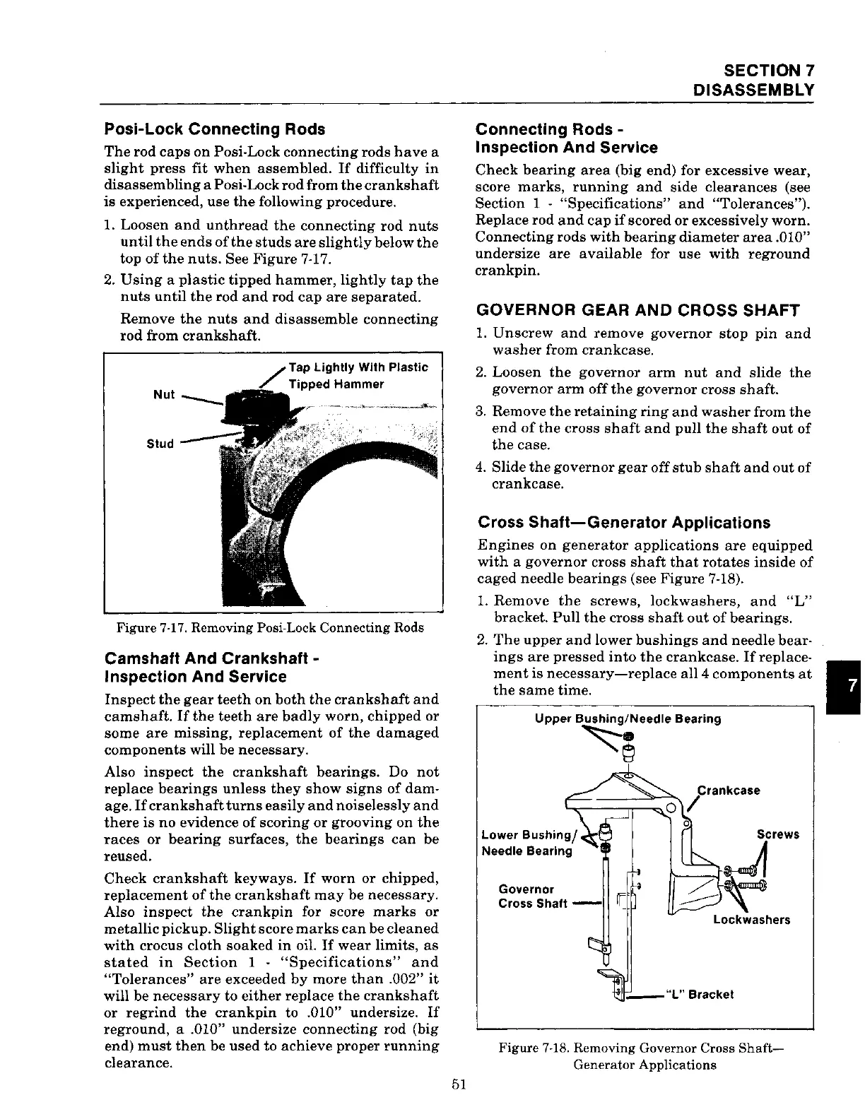
1. Loosen
and
unthread
the
connecting
rod
nuts
until
the
ends
of
the
studs
are
slightly
below
the
top
of
the
nuts.
See
Figure
7-17.
2.
Using
a
plastic
tipped
hammer,
lightly
tap
the
nuts
until
the
rod
and
rod
cap
are
separated.
Remove
the
nuts
and
disassemble
connecting
rod
from
crankshaft.
Tap
Lightly
With
Plastic
Nut
Stud
Figure 7-17. Removing Posi-Lock Connecting Rods
Camshaft And Crankshaft -
Inspection And Service
Inspect
the
gear
teeth
on
both
the
crankshaft
and
camshaft.
If
the
teeth
are
badly
worn,
chipped
or
some
are
missing,
replacement
of
the
damaged
components
will
be
necessary.
Also
inspect
the
crankshaft
bearings.
Do
not
replace
bearings
unless
they
show
signs
of
dam-
age.
If
crankshaft
turns
easily
and
noiselessly
and
there
is
no
evidence
of
scoring
or
grooving
on
the
races
or
bearing
surfaces,
the
bearings
can
be
reused.
Check
crankshaft
keyways.
If
worn
or
chipped,
replacement
of
the
crankshaft
may
be
necessary.
Also
inspect
the
crankpin
for score
marks
or
metallic
pickup.
Slight
score
marks
can
be
cleaned
with
crocus
cloth
soaked
in
oil.
If
wear
limits,
as
stated
in
Section
1 -
"Specifications"
and
"Tolerances"
are
exceeded
by
more
than
.002"
it
will
be
necessary
to
either
replace
the
crankshaft
or
regrind
the
crankpin
to .010" undersize.
If
reground,
a .010"
undersize
connecting
rod (big
end)
must
then
be used to
achieve
proper
running
clearance.
51
Connecting
Rods-
Inspection And Service
SECTION
7
DISASSEMBLY
Check
bearing
area
(big end) for excessive
wear,
score
marks,
running
and
side
clearances
(see
Section 1 - "Specifications" and "Tolerances").
Replace
rod
and
cap
if
scored
or
excessively
worn.
Connecting
rods
with
bearing
diameter
area
.010"
undersize
are
available
for use
with
reground
crankpin.
GOVERNOR GEAR AND CROSS SHAFT
1.
Unscrew
and
remove
governor
stop
pin
and
washer
from
crankcase.
2.
Loosen
the
governor
arm
nut
and
slide
the
governor
arm
off
the
governor
cross
shaft.
3.
Remove
the
retaining
ring
and
washer
from
the
end
of
the
cross
shaft
and
pull
the
shaft
out
of
the
case.
4.
Slide
the
governor
gear
off
stub
shaft
and
out
of
crankcase.
Cross
Shaft-Generator
Applications
Engines
on
generator
applications
are
equipped
with
a
governor
cross
shaft
that
rotates
inside
of
caged
needle
bearings
(see
Figure
7-18).
1.
Remove
the
screws,
lockwashers,
and
"L"
bracket.
Pull
the
cross
shaft
out
of
bearings.
2.
The
upper
and
lower
bushings
and
needle
bear-
ings
are
pressed
into
the
crankcase.
If
replace-
ment
is
necessary-replace
all4
components
at
the
same
time.
Upper
Bushing/Needle
Bearing
~~
Lower
Bushingj
Needle Bearing
Governor
Cross Shaft -
Lockwashers
Figure 7-18. Removing Governor Cross
Shaft-
Generator Applications
 Loading...