Starter System
6132 690 03 Rev. I KohlerEngines.com
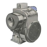
Armature
Components and Details
A
B
A Commutator O.D. B Mica Insulation
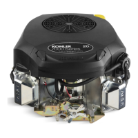
D
E
C
C Insulation Check D Armature Coil
E Continuity Check
1. Clean and inspect commutator (outer surface). Mica
insulation must be lower than commutator bars
(undercut) to ensure proper operation of
commutator.
2. Use an ohmmeter set to Rx1 scale. Touch probes
between 2 different segments of commutator, and
check for continuity. Test all segments. Continuity
must exist between all or armature is bad.
3. Check for continuity between armature coil
segments and commutator segments. There should
be no continuity. If continuity exists between any 2
armature is bad.
4. Check armature windings/insulation for shorting.
Shift Fork
Check that shift fork is complete, and pivot and contact
areas are not excessively worn, cracked, or broken.
Brush Replacement
4 brushes and springs are serviced as a set. Use a new
Kohler brush and spring kit if replacement is necessary.
1. Perform steps 1-5 in Starter Disassembly.
2. Remove screws securing brush holder assembly to
end cap (plate). Note orientation for reassembly later.
Discard old brush holder assembly.
3. Clean component parts as required.
New brushes and springs come preassembled in a
brush holder with a protective sleeve that will also
serve as an installation tool.
4. Perform steps 10-13 in Starter Reassembly
sequence. If starter has been disassembled,
installation must be done after armature, drive lever,
and frame are installed.
Starter Reassembly
NOTE: Always use a new retainer. Do not reuse old
retainers that have been removed.
NOTE: Correctly installed, center pivot section of drive
lever will be fl ush or below machined surface of
housing.
1. Apply drive lubricant to armature shaft splines. Install
drive pinion onto armature shaft.
2. Install and assemble stop collar/retainer assembly.
a. Install stop collar down onto armature shaft with
counter bore (recess) up.
b. Install a new retainer in larger (rear) groove of
armature shaft. Squeeze with a pliers to
compress it in groove.
c. Slide stop collar up and lock it into place, so
recess surrounds retainer in groove. If necessary,
rotate pinion outward on armature splines against
retainer to help seat collar around retainer.
3. Install offset thrust (stop) washer so smaller offset of
washer faces retainer/collar.
4. Apply a small amount of oil to bearing in drive end
cap, and install armature with drive pinion.
5. Lubricate fork end and center pivot of drive lever
with drive lubricant. Position fork end into space
between captured washer and rear of pinion.
6. Slide armature into drive end cap and at same time
seat drive lever into housing.
7. Install rubber grommet into matching recess of drive
end cap. Molded recesses in grommet should be
out, matching and aligned with those in end cap.
8. Install frame, with small notch forward, onto
armature and drive end cap. Align notch with
corresponding section in rubber grommet. Install
drain tube in rear cutout, if it was removed
previously.
9. Install fl at thrust washer onto commutator end of
armature shaft.
10. Starter reassembly when replacing brushes/brush
holder assembly:
a. Hold starter assembly vertically on end housing,
and carefully position assembled brush holder
assembly, with supplied protective tube, against
end of commutator/armature. Mounting screw
holes in metal clips must be up/out. Slide brush
holder assembly down into place around
commutator, and install positive (+) brush lead
grommet in cutout of frame. Protective tube may
be saved and used for future servicing.
Starter reassembly when not replacing brushes/
brush holder assembly:
a. Carefully unhook retaining caps from brush
assemblies. Do not lose springs.
b. Position brushes back in their slots so they are
fl ush with I.D. of brush holder assembly. Insert
brush installation tool (with extension), or use
tube described above from a prior brush
installation, through brush holder assembly, so
holes in metal mounting clips are up/out.
 Loading...