TP-6881 7/1576 Section 5 Component Testing and Adjustment
5.3 Alternator Excitation
Hazardous voltage.
Can cause severe injury or death.
Operate the generator set only when
all guards and electrical enclosures
areinplace.
Moving parts.
WARNING
Servicing the generator set when it is operating. Exposed
moving parts can cause severe injury or death. Keep
hands, feet, hair, clothing, and test leads away from the belts
and pulleys when the generator set is running. Replace
guards, screens, and covers before operating the generator
set.
Testing live electrical circuits. Hazardous voltage or
current can cause severe injury or death. Have trained and
qualified personnel take diagnostic measurements of live
circuits. Use adequately rated test equipment with electrically
insulated probes and follow the instructions of the test
equipment manufacturer when performing voltage tests.
Observe the following precautions when performing voltage
tests: (1) Remove all jewelry. (2) Stand on a dry, approved
electrically insulated mat. (3) Do not touch the enclosure or
components inside the enclosure. (4) Be prepared for the
system to operate automatically.
(600 volts and under)
Short circuits. Hazardous voltage/current can cause
severe injury or death. Short circuits can cause bodily injury
and/or equipment damage. Do not contact electrical
connections with tools or jewelry while making adjustments or
repairs. Remove all jewelry before servicing the equipment.
Hot engine and exhaust system.
Can cause severe injury or death.
Do not work on the generator set until
it cools.
WARNING
Servicing the alternator. Hot parts can cause severe
injury or death. Avoid touching the alternator field or exciter
armature. When shorted, the alternator field and exciter
armature become hot enough to cause severe burns.
5.3.1 No to Low Voltage Operation
This section covers the operation of the alternator
excitation and troubleshooting information for low or no
voltage output.
Before beginning the test procedures, read all safety
precautions at the beginning of this manual. Many of the
test procedures include additional safety precautions.
After crank disconnect, controller will disengage the
flash relay when the AC output of the generator reaches
1/4 of the output voltage. At this level, the output on the
auxiliary windings should have reached a level sufficient
to self-excite the a lternator rotor field. If the output
voltage does not exceed 1/3 of rated voltage, the
generator is only producing voltage using the flash
relay. To further isolate the cause of this failure:
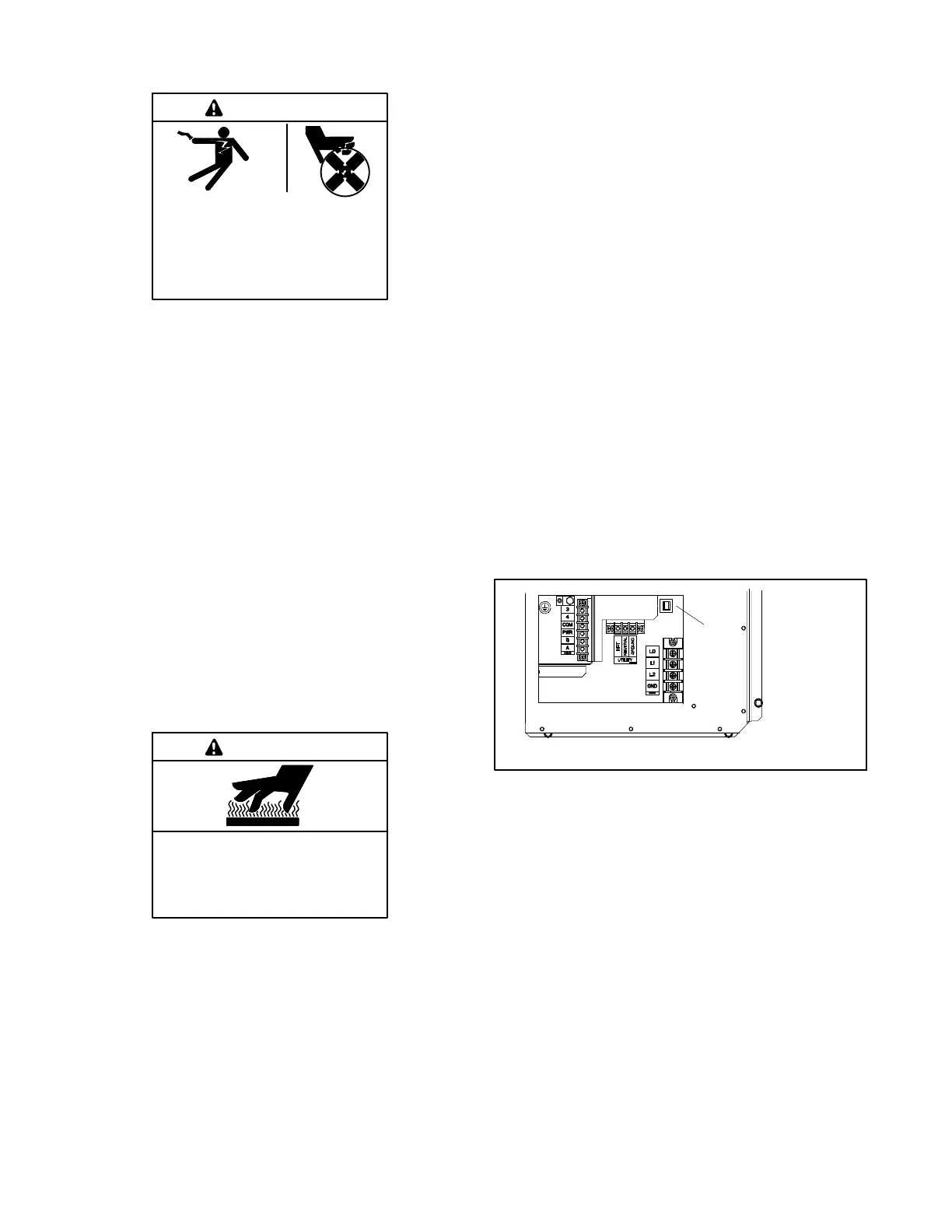
1. Check the condition of the auxiliary winding circuit
breaker. The circuit breaker is located in the
connection area of the junction box. If this breaker
is open, the auxiliary winding current will not be
able to reach the field and the field will only be
supplied by the flash relay. If the breaker is tripped,
stop the generator, d isconnect P2 and verify no
continuity between ground and each of 55, 66, FP,
FN.
1. Auxiliary winding circuit breaker (Mini-breaker)
1
Figure 5-2 Connection Area (cover removed)
2. Verify the connections for 55, 55F and 66 per
Figure 5-1.
3. Reconnect P2, start the generator and check for
voltage between 55 and 66. This voltage should
exceed 30 Volts AC when the AC output voltage is
above 60 Volts AC. If the voltage does not exceed
30 VAC, stop the generator and complete the rotor
and stator checks in Sections 5.4 and 5.5.
4. Check DC voltage between FP and FN. If this
voltage is above 20 VDC, stop the generator and
complete the rotor and stator checks in Sections
5.4 and 5.5.
5. If the auxiliary winding voltage exceeds 30 VAC
and the field voltage does not exceed 20 VDC,
replace the generator controller.

 Loading...