TP-6881 7/15 79Section 5 Component Testing and Adjustment
Stator Continuity and Resistance Tests
1. Press the OFF button on the controller to turn off
the generator set.
2. Disconnect u tility power to the generator set.
3. Disconnect the generator set engine starting
battery, negative (--) lead first.
4. Disconnect all stator leads before performing all
stator tests.
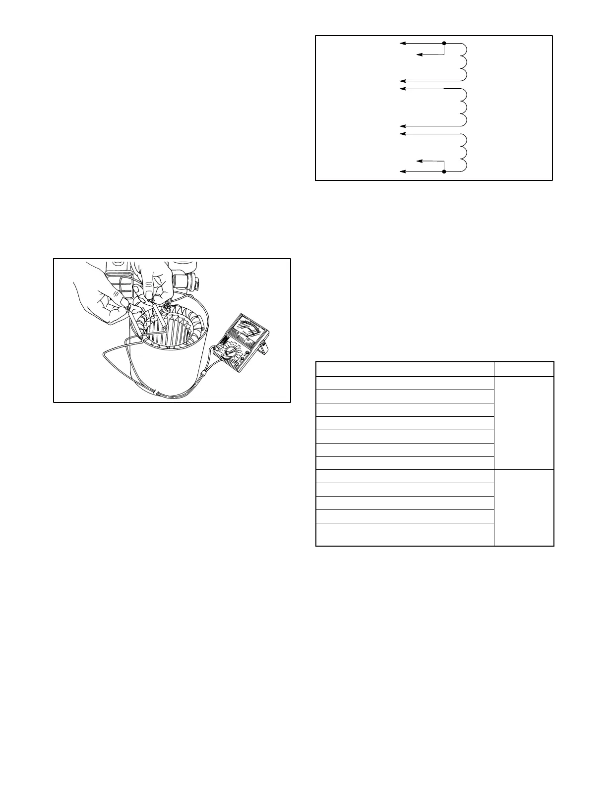
5. To check for stator continuity, set the ohmmeter on
R x 1 scale. First set the ohmmeter zero by holding
the red and black meter leads together and setting
the ohmmeter reading to zero. Then check the
stator continuity by connecting the meter leads to
the stator leads as shown in Figure 5-4.
R14807-14
Figure 5-4 Testing Stator Windings
Note: For single-phase models, leads 1, 2, 3, and 4 are
the generator output leads. Leads 11, 44, 55, and
66 are the controller sensing and supply leads.
Refer to the schematic in Figure 5-5 when
performing the following steps.
3
4
55
2
1
44
11
6196
66
Figure 5-5 Single-Phase Alternator Stator Leads
6. Contact the ohmmeter leads and readjust the
ohmmeter to read zero ohms.
7. Check the cold resistance of the stator windings by
connecting the meter leads to stator leads 1-2, 3-4,
and 55-66. See Section 1.5, Alternator
Specifications, for stator winding resistances.
Most ohmmeters do not provide accurate readings
below 1 ohm. Low resistance readings (continuity)
and no evidence of shorted w indings (heat
discoloration) indicate a stator in good condition.
SeeFigure5-6.
Leads Continuity
1 and 2
Yes
1 and 11
2 and 11
3 and 4
3 and 44
4 and 44
55 and 66
1 and 3, 4, 44, 55, or 66
No
2 and 3, 4, 44, 55, or 66
3 and 1, 2, 11, 55, or 66
4 and 1, 2, 11, 55, or 66
Any stator lead and ground on stator
housing or frame laminations
Figure 5-6 Continuity Te st Results on a Good Stator
(single-phase)

 Loading...