44 TP-7091 4/23
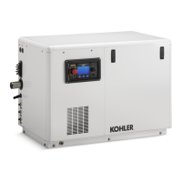
Figure 32 Accessory Module Connections (three cable runs with one module each)
1. Generator Set Terminal Block. Check the decal on the generator set for terminal block connections.
2. Splice.
3. Connect all of the shield leads on this end to GROUND at the generator set.
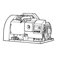
Figure 33 Multiple Connections to the Generator Set
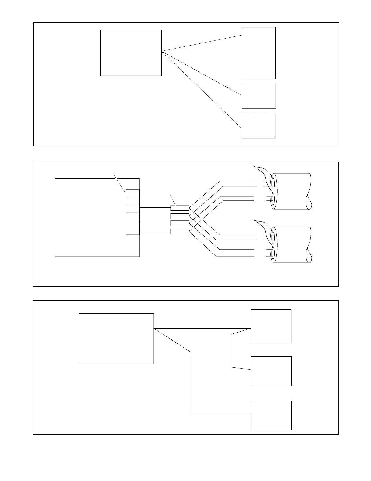
Figure 34 Accessory Module Connections (two cable runs with one and two modules shown)
Check the decal on the generator set for terminal block connections.
3 runs with 1 module each shown.
for communication connection detail (A and B, PWR and
Use splices or wire nuts to collect multiple leads for connection to the
generator set terminal block. See Figure 33.
Check the decal on the generator set for terminal block
connections.
See the Communication Cable Specifications section.
See Figure 30 for communication connection detail (A and B,
PWR and COM). Connect the cable shield to ground at the
generator set.
• Use splices or wire nuts to collect multiple leads for connection
to the generator set terminal block. See Figure 33.
 Loading...