24
Governor System
KohlerEngines.com 18 690 06 Rev. --
GOVERNOR
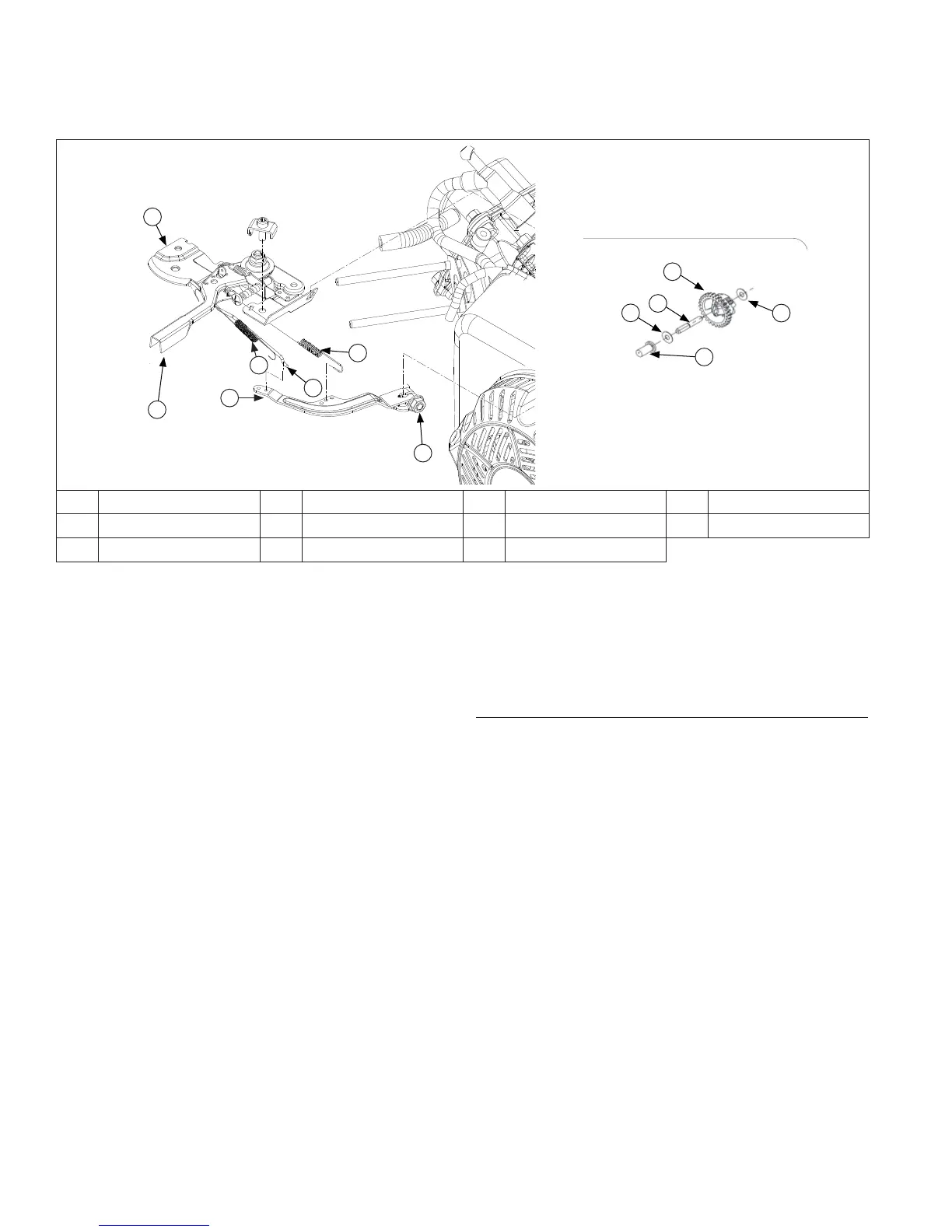
Governor Components
G
E
I
J
K
I
H
B
C
D
F
A
A Control Assembly B Nut C Governor Spring D Throttle Link
E Dampening Spring F Throttle Control Lever G Governor Lever H Cup
I Washer J Governor Gear K Governor Gear Shaft
● When load is applied and engine speed and governor
gear speed decreases, governor spring tension moves
governor arm to open throttle plate wider. This allows
more fuel into engine, increasing engine speed. As
speed reaches governed setting, governor spring
tension and force applied by regulating pin will again
offset each other to hold a steady engine speed.
Governor Adjustments
Initial Adjustment Procedure
NOTE: Make sure carburetor is mounted and secured in
place when adjustment is being made/checked.
Make this initial adjustment whenever governor lever
is loosened or removed from cross shaft. To ensure
proper setting, make sure throttle linkage is connected to
governor lever and to carburetor throttle lever.
Adjust as follows:
1. Remove air cleaner cover.
2. Then either reposition fuel tank to access governor
shaft and lever joint, or disconnect fuel line and
remove tank from engine.
3. Loosen governor lever mounting nut.
4. Move governor lever clockwise until it stops.
5. Rotate governor shaft clockwise until it stops.
6. Hold both in this position and torque governor lever
nut to 7 N·m (62 in. lb.).
Governed speed setting is determined by position of
throttle control. It can be variable or constant, depending
on engine application.
Governor is designed to hold engine speed constant
under changing load conditions. Most engines are
equipped with a centrifugal fl yweight mechanical
governor. Governor gear/fl yweight mechanism of
mechanical governor is mounted inside crankcase and is
driven off gear on crankshaft.
This governor design works as follows:
● Centrifugal force acting on rotating governor gear
assembly causes fl yweights to move outward as
speed increases. Governor spring tension moves
them inward as speed decreases.
● As fl yweights move outward, they cause regulating pin
to move outward.
● Regulating pin contacts tab on cross shaft causing
shaft to rotate.
● One end of cross shaft protrudes through crankcase.
Rotating action of cross shaft is transmitted to throttle
lever of carburetor through external throttle linkage.
● When engine is at rest, and throttle is in fast position,
tension of governor spring holds throttle plate open.
When engine is operating, governor gear assembly is
rotating. Force applied by regulating pin against cross
shaft tends to close throttle plate. Governor spring
tension and force applied by regulating pin balance
each other during operation, to maintain engine
speed.
 Loading...