50 Disassembly and assembly SEN04128-01
PC130-8
49
Removal and installation of swing
circle assembly 1
Removal
k Gradually loosen the hydraulic oil tank cap
to bleed the air from the tank after ground-
ing the work equipment and stopping the
engine and lock the safety lock lever.
1. Remove the revolving frame assembly by
referring to
"Removal of revolving frame
assembly".
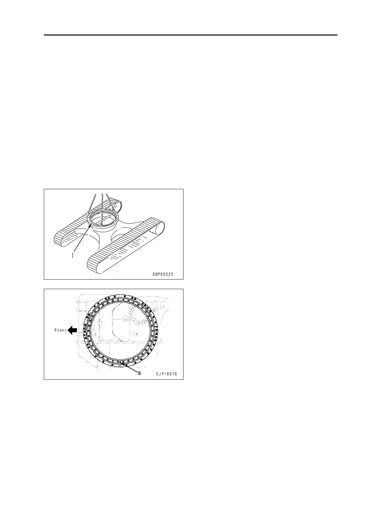
2. Temporarily lift swing circle assembly (1) to
r
emove the 38 mounting bolts. [*1]
3. Remove swing circle assembly (1). [*2]
4 Swing circle assembly : 155 kg
Installation
q Installation is performed in the opposite way to
removal.
[*1]
2 Swing circle mounting bolt:
Liquefied adhesive (LT-2)
3 Swing circle mounting bolt :
245 – 308.9 Nm {25 – 31.5 kgm}
[*2]
a Lif
t swing circle assembly (1) and install it on
the track frame with the inner wheel soft zone
"S" symbol (a) of the inner race facing the right
side of the body as shown in the figure.
2 Amount of circle grease sealed: 9.1 l
grease (G2-LI)

 Loading...