SEN04130-01 50 Disassembly and assembly
12 PC130-8
Removal and installation of
control valve assembly 1
Removal
k Stop the machine on a level ground, lower
the work equipment to the ground, stop the
engine, and set the lock lever in the lock
position.
k Disconnect the cable from the negative (–)
terminal of the battery.
k Loosen the hydraulic tank cap gradually to
release the pressure in the hydraulic tank.
a Put t
ags to the pipings to prevent a mistake in
re-connecting them.
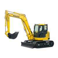
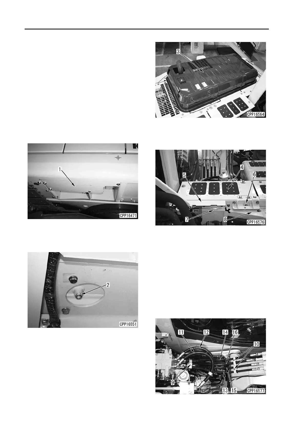
1. Remove undercover (1).
2. Loosen hydraulic oil drain plug (2) and drain
the hydraulic oil. [*1]
6 Hydraulic tank: 90 l
(Specified quantity of oil): 14
5 l
3. Open and lock engine hood (3).
4. Remove cover (4).
5. Remove brackets (5) and (6) and covers (7)
a
nd (8).
6. Remove clamps (9) and (10).
7. Disconnect front upper hoses (11) - (16).
(Port Nos. and connection points)
(11) Control valve (A7) - To attachment 1
(12) Control valve (B7) - To attachment 1
(13) Control valve (A6) - To bucket head side
(14) Control valve (B6) - To bucket bottom side
(15) Control valve (A5) - To arm head side
(16) Control valve (B5) - To arm bottom side
a Discon
nect hoses (11) – (14) from the
control valve.
a Discon
nect hose (15) from the work equip-
ment and then disconnect it from the con-
trol valve.

 Loading...