302 Troubleshooting by failure code, Part 2
Failure code [CA2185] Throt Sens Sup Volt High Error
40-302 48 PC200, 200LC, 220, 220LC-8M0
SEN06134-00
Failure code [CA2185] Throt Sens Sup Volt High Error
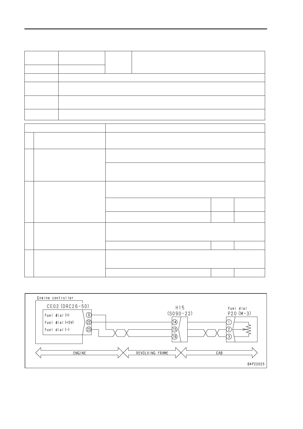
Circuit diagram related to throttle sensor
Action
level
Failure code
Failure
Throttle Sensor Power Supply Voltage High Error
(Engine controller system)
L03 CA2185
Detail of failure
q High voltage (5.25 V or higher) appears in throttle sensor power supply circuit.
Action of con-
troller
q Sets throttle position by using signal other than throttle sensor signal and allows engine to run.
Problem on
machine
q Engine speed cannot be controlled by fuel control dial.
Related infor-
mation
q Method of reproducing failure code: Turn starting switch to ON position.
Cause Procedure, measuring location, criteria and remarks
1
Defective wiring harness connec-
tor
See descriptions of wiring harness and connectors in "c: Electrical equipment"
in "Checks before troubleshooting" of "General information on troubleshoot-
ing", and check them.
2
Defective throttle sensor (fuel con-
trol dial)
1. Turn starting switch to OFF position.
2. Disconnect connector P20, and turn starting switch to ON position.
If this failure code is not displayed, throttle sensor is defective.
a Other failure codes are displayed, too. This is because connector is discon-
nected. Ignore failure codes other than [CA2185].
3 Short circuit in wiring harness
1. Turn starting switch to OFF position.
2. Disconnect connectors CE02, CE03 and P20, and connect T-adapters to
each female side of CE02 and CE03.
Between CE02 (female) (22) and each pin other
than (22)
Resis-
tance
Min. 1 Mz
Between CE02 (female) (22) and CE03 (female) (3)
Resis-
tance
Min. 1 Mz
4
Hot short circuit in wiring harness
(contact with 24 V circuit)
1. Turn starting switch to OFF position.
2. Disconnect connector P20 and connect T-adapters to female side.
3. Turn starting switch to ON position.
Between P20 (female) (1) and ground Voltage 4.75 to 5.25V
5 Defective engine controller
1. Turn starting switch to OFF position.
2. Disconnect connector CE02, and connect T-adapters to male side.
3. Turn starting switch to ON position with wiring harness disconnected.
Between CE02 (male) (22) and (23) Voltage 4.75 to 5.25V
 Loading...