SEN03856-00
WA250, 250PZ-6 50-500 55
500 Hydraulic system
Removal and installation of hydraulic tank
Removal and installation of
hydraulic tank
1
Removal
k Stop the machine on a level ground and set
the lock bar to the frame to fix the front and
rear frames.
k Lower the work equipment to the ground,
stop the engine, apply the parking brake,
and put chocks under the tires.
k Operate the work equipment control lever 2
– 3 times to release the residual pressure in
the work equipment circuit.
1. Open and fix right engine side cover (1).
a Check that the cover is locked securely.
2. Remove right fender (2).
4 Fender: 25 kg
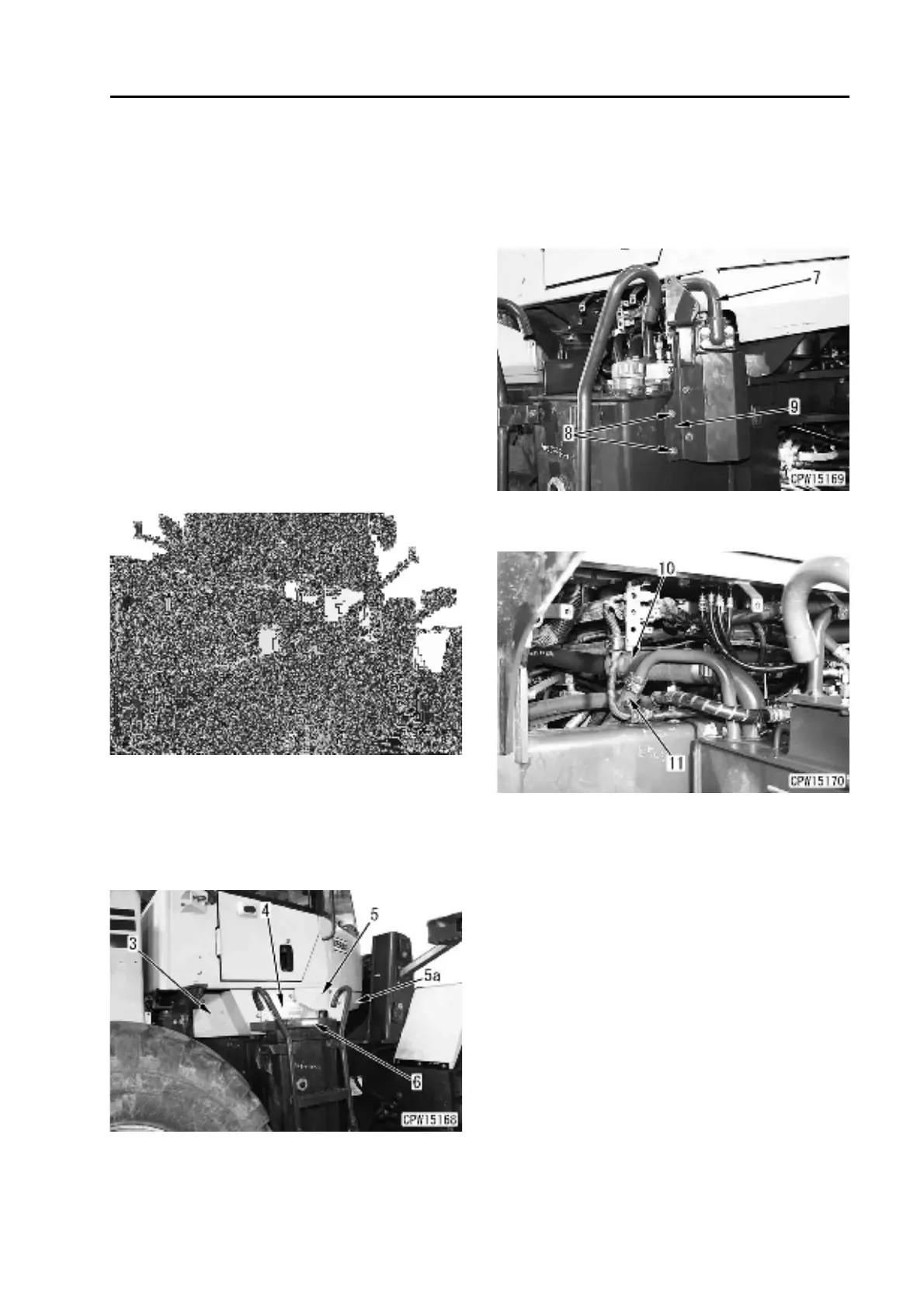
3. Remove covers (3), (4) and (5).
4. Remove hydraulic tank cover (6).
k Loosen the hydraulic tank cap gradu-
ally to release the pressure in the
hydraulic tank.
5. Remove tube (7) between the hydraulic tank
and hydraulic oil filter.
6. Remove 2 mounting bolts (8) and bracket (9).
a Fix the bracket and hydraulic oil filter to
the machine with ropes.
7. Disconnect suction hose (10) and return hose
(11) from the hydraulic tank tube. [*1]
 Loading...