This document is a field assembly manual for the Komatsu WA600-3 Wheel Loader, specifically for serial numbers WA600-3 50001 and up. It outlines the procedures for assembling the various components of the wheel loader after delivery.
Function Description
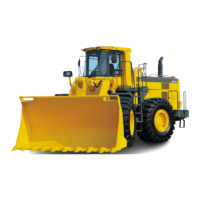
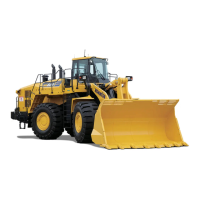
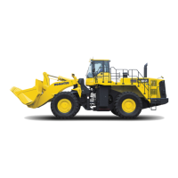
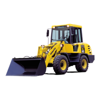
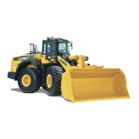
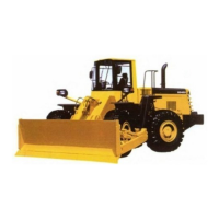
The Komatsu WA600-3 is a heavy-duty wheel loader designed for various earthmoving and material handling applications. Its primary function is to scoop, lift, and transport loose materials such as sand, gravel, soil, and aggregates. The assembly manual details the process of integrating the main components, including the bare machine, bucket, tires and wheels, cab, and ROPS canopy, to prepare the loader for operation.
Important Technical Specifications
The manual provides a "Weight and Dimensions Table of Units Divided for Delivery," offering key specifications for the main components:
- Bare machine:
- Weight: 29,500 kg
- Overall length: 9,270 mm
- Overall width: 3,500 mm
- Overall height: 3,000 mm
- Bucket assembly:
- Weight: 4,000 kg
- Overall length: 3,700 mm
- Overall width: 1,900 mm
- Overall height: 2,000 mm
- Tire and wheel assembly:
- Weight: 1,700 kg
- Overall length: 2,100 mm
- Overall width: 2,100 mm
- Overall height: 900 mm
- Cab assembly:
- Weight: 440 kg
- Overall length: 1,800 mm
- Overall width: 1,500 mm
- Overall height: 1,700 mm
- ROPS canopy assembly:
- Weight: 810 kg
- Overall length: 1,800 mm
- Overall width: 2,200 mm
- Overall height: 1,800 mm
The manual also specifies tightening torques for critical components:
- Tire and wheel assembly nuts: 735–911 Nm {75–93 kgm}, with a target value of 823 Nm {84 kgm}.
- ROPS canopy mounting bolts: 1520–1910 Nm {155–195 kgm}, with a target value of 1715 Nm {175 kgm}.
For the steering wheel, the operating effort is specified as 0.7–1.3 kg, measured tangentially with a push-pull gauge.
Usage Features
The manual focuses on the assembly process rather than operational features, but it implicitly highlights aspects relevant to the loader's design and functionality:
- Modular Design: The loader is delivered in distinct units (bare machine, bucket, tires, cab, ROPS canopy), indicating a modular design that facilitates shipping and on-site assembly.
- ROPS Canopy: The inclusion of a ROPS (Roll-Over Protective Structure) canopy emphasizes operator safety, a critical feature for heavy machinery.
- Steering System: The detailed steps for installing the cab and adjusting the steering post, including the measurement of steering wheel operating effort, suggest a focus on ergonomic and precise steering control for the operator.
- Bucket Attachment: The multi-step process for installing the bucket, including shim selection and grease application, indicates a robust and adjustable attachment mechanism designed for heavy loads and durability.
- Maintenance Access (Implied): The removal and reinstallation of covers (e.g., floor frame undercovers, cab covers) during assembly suggest designed access points for future maintenance and inspection.
Maintenance Features
While primarily an assembly guide, the manual touches upon several points that are relevant to future maintenance:
- Grease Application: The instruction to apply LM-G (lithium grease containing molybdenum disulfide) to the bucket hinge pin and bucket link pin during assembly highlights the importance of lubrication for wear prevention and smooth operation. This suggests that regular greasing will be a key maintenance task.
- Sealant Use: The use of CEMEDINE 366E or equivalent sealant for the cab seal, antenna screw holes, and antenna wire hole grommet indicates a design consideration for weatherproofing and preventing water ingress, which is crucial for protecting electrical components and the operator's environment. This implies that seals and sealants should be inspected and potentially reapplied during maintenance.
- Component Tightening: The specified tightening torques for various bolts (tires, ROPS canopy, steering post) are critical for structural integrity and safety. Regular torque checks would be a standard maintenance procedure.
- Shim Adjustments: The detailed procedures for selecting and installing shims for the bucket hinge pin and retainer indicate that these components are designed for precise fit and wear compensation, allowing for adjustments to maintain optimal performance over time.
- Accessibility: The temporary removal of covers and the detailed steps for connecting wiring and tubes during assembly suggest that these areas are designed with a degree of accessibility for future troubleshooting and repair.
- Troubleshooting Switch: The installation of a "troubleshooting switch" within the cab implies built-in diagnostic capabilities to aid in identifying and resolving operational issues, simplifying future maintenance and repair efforts.