EN
UAB KOMFOVENT we reserve the right to make changes without prior notice
C5.1_22- 08
12
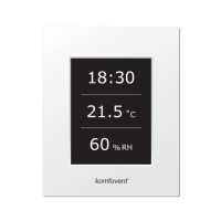
2.5.2.6. Override function
Override (OVR) control of the unit can be performed by the external con-
tact (see Picture 1.3 b) or device (timer, switch, thermostat, etc.). The received
signal from the outside activates the OVR function, which ignores the current
operation modes of the unit and performs one of the selected actions listed
below:
• switches o the air handling unit;
• switches over the unit to operation according to the mode “Comfort1”;
• switches over the unit to operation according to the mode “Comfort2”;
• switches over the unit to operation according to the mode “Economy1”;
• switches over the unit to operation according to the mode “Economy2”;
• switches over the unit to operation according to the mode “Special”;
• switches over the unit to operation according to the weekly schedule.
The OVR function provides for three operation modes selectable depending on the needs of the
user:
1. The mode “When on” – the function will respond to the external control contact only when the air
handling unit is on.
2. The mode “When o” – the function will respond to the external control contact only when the air
handling unit is o.
3. The mode “Always” – the function will respond to the external control contact irrespective of the
operating condition of the unit.
The OVR function has the top priority and, therefore, ignores all previous modes.
The function remains active as long as the external control contact is in the closed
position.
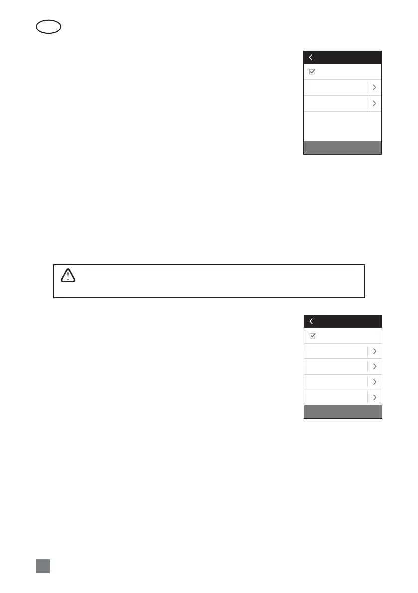
2.5.2.7. Humidity control
Humidity control function is designed for maintenance of air humidity de-
termined by the user. For proper operation of the function one or two addi-
tional humidity sensors shall be connected, depending on where humidity will
be maintained. There are two modes for maintenance of humidity:
• Supply air. The determined humidity of supply air is maintained, using the
supply air duct humidity sensor (B9).
• Room air. The determined humidity of indoor air is maintained, using the
room air or exhaust air duct humidity sensor (B8). The supply air humidity
limit is set using the duct humidity sensor or hydrostat (B9).
One of the below methods can be chosen for maintenance of the deter-
mined humidity:
• Humidication of air. There is a control signal of 0...10 V, directly reecting the capacity of the hu-
midier from 0 to 100 %. If humidication is required, the control is transferred through the output
TG3 of the controller.
• Dehumidication of air. There is a control signal of 0...10 V, directly reecting the capacity of the
dehumidier from 0 to 100 %. If dehumidication is required, the control is transferred through the
output TG3 of the controller.
• Dehumidication of air: cooling-heating. Dehumidication is performed using the coolers and
heaters available in the air handling unit. If there are several coolers and heaters, then it shall be pre-
-determined which of them will be used in the dehumidication process.
• Humidication and dehumidication of air. For humidication of air the control signal of 0...10 V
is used through the output TG3 of the controller, and the dehumidication of air is performed using
the coolers and heaters available in the unit.
Reset settings
Enable
Override
If on
Mode
ECONOMY 1
Override function
Reset settings
Enable
Setpoint 1
55% RH
Mode 1
COMFORT 1
Setpoint 2
30% RH
Mode 2
ECONOMY 2
Humidity control
 Loading...