UAB KOMFOVENT we reserve the right to make changes without prior notice
C5.1_22- 08
5
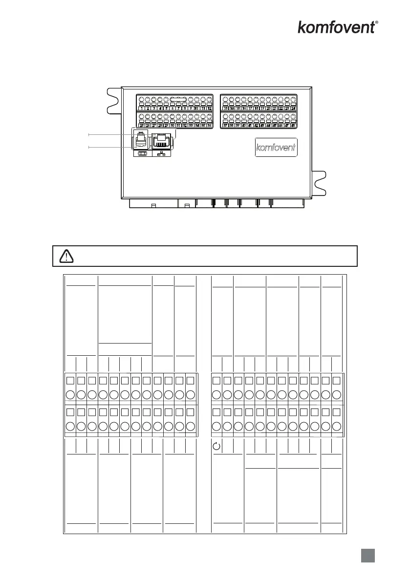
1.3. External Elements Connection
The air handling unit is designed with external connection terminals which are located on the con-
troller box, inside the air handling unit. All external control elements are connected to the terminals.
1
2
1. „Ethernet“ computer network or internet connection
2. Control panel connection
1.3 a Picture. Controller with connection terminals
Total power of all external elements with 24V supply may not exceed 15W.
37 38 39 40 41 42 43 44 45 46 47 48
13 14 15 16 17 18 19 20 21 22
~24V
~24V
~24V
GND
0..10V
0..10V
0..10V
NO
NO
NO
NO
NO
C
C
DX
Indication
control
Cold water
mixing valve /
DX capacity control
Hot water
Cooling water
Heating water
pump
230V AC, 1A
pump 230V AC, 1A
mixing valve
actuator
Humidifier
Run
Alarm
Common
Common
TG3 TG2 TG1 S1S2
IN5
L
L
N
N
N
N
N
23 24
25 26 27 28 29 30 31 32 33 34 35 36
~24V
~24V
~24V
~24V
0..10V
0..10V
0..10V
0..10V
C
NTC
B5
MODBUS
RS485
connection
OVR control
Common
Return water
Supply air
temperature sensor
temperature sensor
Fire system
External stop
Control input
External control
B1
NTC
A
GND
IN4
IN3
IN2
IN1
B
N
N
N
N
1234
5
6
7
8910 11 12
Water pump /
coil alarm
C
DX3 / Heating
DX2 / Cooling
DX1/ Start
Air damper
actuator
Supply air
pressure sensor
Exhaust air
pressure sensor
Air quality sensor
Humidity sensor
1.3 b Picture. External control elements connection
 Loading...