EN
UAB KOMFOVENT we reserve the right to make changes without prior notice
C5.1_22- 08
18
2.8. Troubleshooting
If the unit fails to operate:
• Make sure that the unit is connected to the power supply network.
• Check whether the main switch (if designed) is turned on.
• Check all fuses of the automatics. If necessary, replace blown-out fuses with new ones having the
same electrical parameters (the sizes of the fuses are indicated on the schematic electrical diagram).
• Check whether there is any failure message on the control panel. If there is indication, it needs to be
eliminated rst. In order to eliminate the failure, follow the table.
• If nothing is indicated on the control panel, check whether cable connecting control panel with the
unit is not damaged.
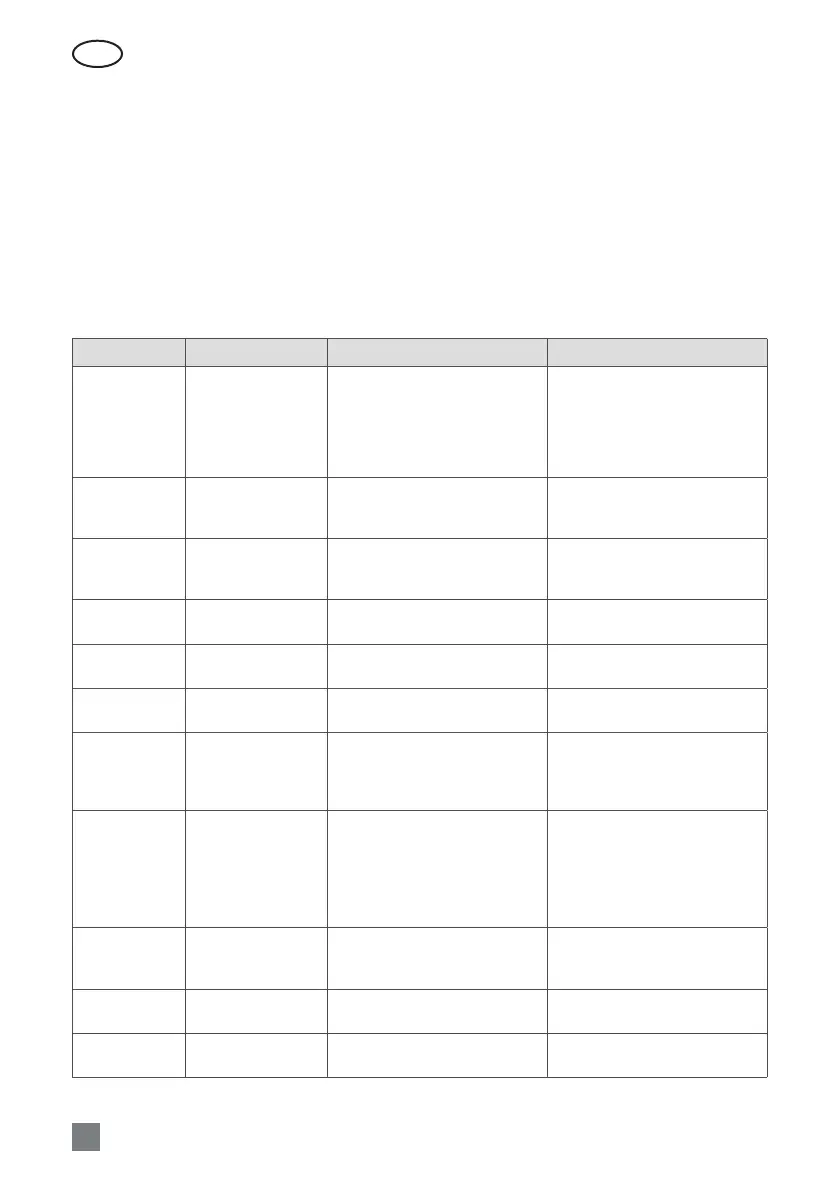
2.8 Table. Alarms indicated on the control panel, their possible causes and elimination methods
Code Message Possible cause Elimination
14B Service time
If unit continuous operation
(without breaks) was 12 months,
then periodic inspection message
appears.
After disconnecting the unit from
power supply, it is necessary to
carry out periodic inspection of
the unit, i.e. to check the condition
of the heat exchanger, the heater
and fans.
1B, 19A Low supply air ow
Too high resistance of the ventila-
tion system.
Check pressure pipes, air dampers,
air lters and make sure that the
ventilation system is not blocked.
2B, 20A Low extract air ow
Too high resistance of the ventila-
tion system.
Check pressure pipes, air dampers,
air lters and make sure that the
ventilation system is not blocked.
3B VAV calibration fail
Pressure sensors are not con-
nected or broken.
Check connections of the sensor or
replace the sensor.
4B
Change outdoor air
lter
The fresh air lter is blocked.
Shut down the unit and replace
the lter.
5B
Change extract air
lter
The extract air lter is blocked.
Shut down the unit and replace
the lter.
6B -11B Electric heater o
The heater is disconnected due to
too low air volume.
As soon as the heater cools down,
protection resets automatically. It
is recommended to increase the
ventilation intensity level.
113B,114B
CF exchanger not
calibrated
CF exchanger calibration not
performed or failed
Make sure that all doors are
closed, there is no obstruc-
tions in the ducts and AHU can
reached airflow setpoint of COM-
FORT 1 mode. Repeat calibration
manually (see2.5.1.3.).
127B Service mode
Temporary mode, which can be
activated by the service personnel.
The service mode is switched
o by simply deleting the alert
message.
1A, 2A
Supply air tempera-
ture sensor failure
The supply air temperature sensor
is not connected or broken.
Check connections of the sensor or
replace the sensor.
3A, 4A
Extract air tempera-
ture sensor failure
The discharged air temperature
sensor is not connected or broken.
Check connections of the sensor or
replace the sensor.
 Loading...