PLAY360
Copyright©KOMPAN A/S
V00050GB 20140814 RikBon/PetrJu
3/19
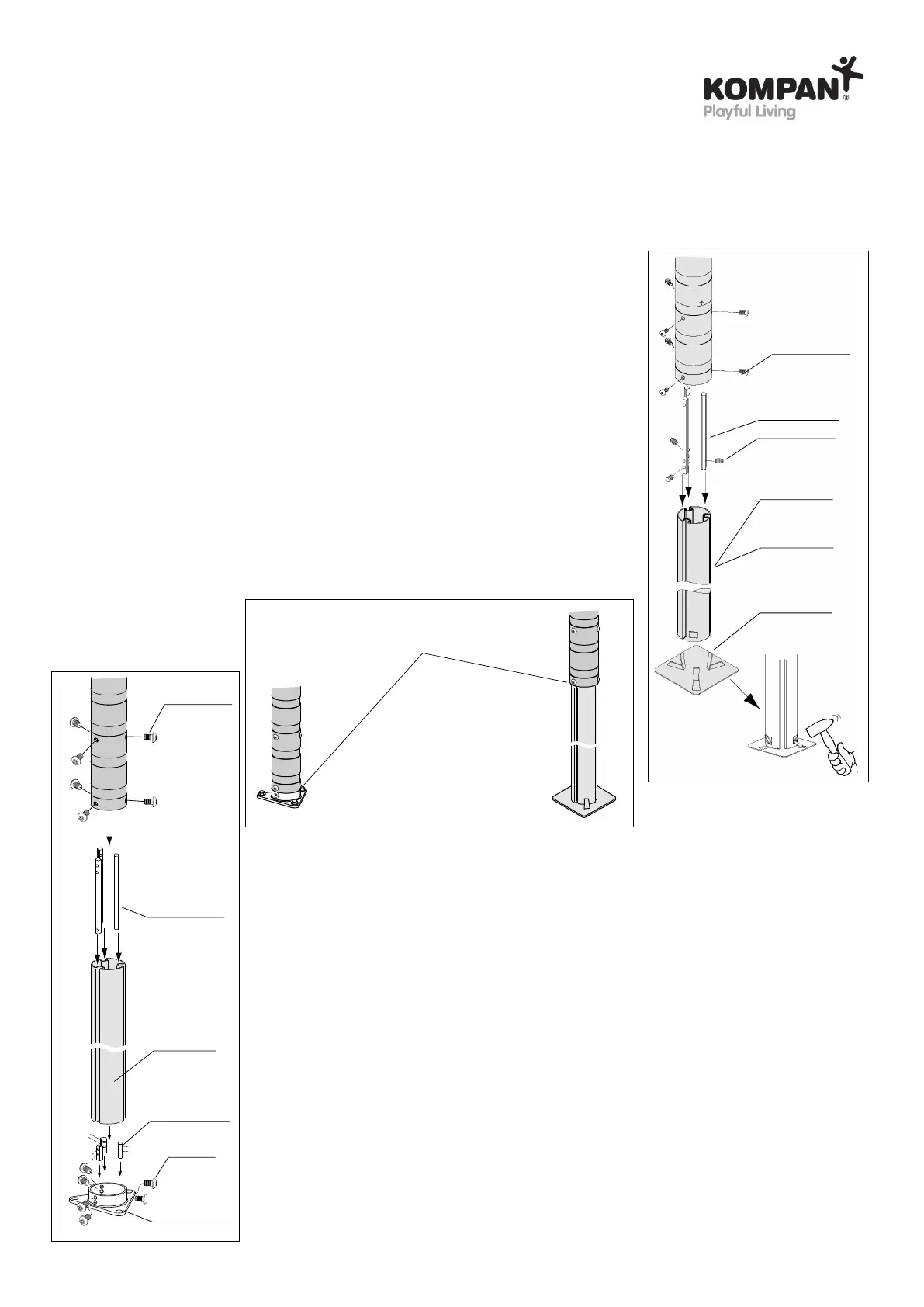
Assembly of post footing for surface installation (ill. 7)
The KOMPAN ELEMENTS surface footing consists of a steel footing profile with 3 wedge
grooves, 3 long aluminium wedges with 3 holes, 3 short aluminium wedges with 2 holes,
and a flange unit.
- Insert the footing profile into the flange, then position the 3 short wedges in the wedge
grooves so that they are flush with the upper edge of the flange and the holes in the
flange and wedges line up. Insert the 8x20 mm screws 910820 in the wedges and
tighten the uppermost and lowermost screws alternately until both are fully tightened
and the footing section has expanded so that it is properly lodged in the flange unit.
- Then insert the long wedges in the wedge grooves so that the wedge ends with 2
holes are opposite the flange. Allow the footing unit to slide into the post so that all six
threaded holes in the wedges are visible through the holes in the sides of the post.
- Then slide six 10x20 mm button head screws 601020-A2 into the wedges.
- It is now possible to adjust the footing unit by loosening the button head screws. Tap
lightly on the screw heads to loosen the wedges from the grooves, adjust the footing
unit to the required position and tighten the screws.
4 Preparing the installation
Assembly of post footing for in-ground anchoring (ill. 6)
The KOMPAN ELEMENTS in-ground footing consists of a steel footing profile with 3
wedge grooves and 3 aluminium wedges that lock in place in the wedge grooves
using set screws. The function of the set screws is to retain the wedges in the wedge
grooves until the footing profile has been installed in the post. The footing is
adjustable and is designed for in-ground anchoring from 70 to max. 90 cm. For
in-ground anchoring of up to max. 120 cm A400441-99 is available.
- Slide the footing unit into the lower end of the post (the part with 6 holes) until
the threaded holes in the wedges are visible through the corresponding holes
in the sides of the post.
- Then insert six 10x20 mm button head screws 601020-A2 into the wedges and
the set screws can now be loosened.
- It is now possible to adjust the footing unit by loosening the button head screws.
Tap lightly on the screw heads to loosen the wedges from the grooves, adjust
the footing unit to the required position and tighten the screws.
90 cm
A400470-51
A400295-128
10x12
911012
120 cm
A400471-51
A400469-51
M10x20
601020-A2
ill. 6
ill. 7
40 cm
A400477-51
A400312-128
A400306-51
A400307-51
M8x20
910820
10x20
601020-A2
A400295-128
Top of safety surface
 Loading...