The provided document is a maintenance manual for the Frydenbö IRV-2 Steering Gear manufactured by Kongsberg.
Function Description
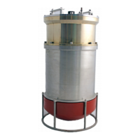
The Frydenbö IRV-2 Steering Gear is a robust hydraulic steering system designed for marine vessels, particularly tankers over 100,000 DWT, to meet IMO's single failure criteria. It comprises two identical power actuating systems housed within a single unit, separated by a double hydraulic sealing system.
The core components include:
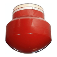
- Actuator: Features a rotor with vanes that generate turning torque when oil pressure is applied. The turning movement is limited by mechanical stoppers, which also serve as hard-over rudder stoppers, and electrical limit switches for precise angle control. The rudder carrier bearing supports the full weight of the rudder, rudderstock, and rotor, lubricated by the system oil. A synthetic oil-resistant sealing system prevents internal and external leakage.
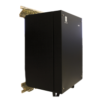
- Power Pack: Consists of two pump units, which can operate separately or combined. One pump unit typically acts as the primary, and the other as a stand-by. Running both pumps simultaneously doubles the turning rate for faster steering.
- Valve Systems: The IRV Steering Gear includes a double set of valves:
- Control Valves (Power Pack): Activated by command to initiate rudder movement.
- Lock Valves (Actuator): Open with increased external pressure and close upon loss of external pressure to maintain actuator integrity, allowing operation by the stand-by pump if needed.
- Isolating Valves (Actuator): Connect the two power actuating systems during normal operation. In case of a system defect, these valves isolate the faulty system, allowing the intact system to continue operation.
- Safety Relief/By-pass Valves (Actuator): Protect against excessive external pressure from the rudder and can bypass a defective system.
Emergency Steering - Automatic Isolation (IMO Function):
The system automatically activates emergency steering mode upon detecting a significant loss of hydraulic oil in one of the systems. This detection is performed by electrical level switches (S20, S21, S22, S25) in the hydraulic Power Pack tank.
- Common Oil Level Switch (S20): Triggers a "Low Oil Level" alarm.
- Low Low Oil Level Switches (S21, S22): If activated, isolation valves close to separate the systems. If both pumps are in operation, steering continues with both systems; however, if only one pump is active, the stand-by pump starts automatically. A "Low Low Oil Level" alarm appears on the defective system, and its bypass valve activates. The pump unit on the defective system must be stopped manually.
The manual also outlines scenarios for system errors not detected by automatic isolation, such as poor rudder response (potentially due to a locked OPEN bypass valve) or complete loss of steering (potentially due to a locked CLOSED bypass valve or locked OPEN isolating valve).
Important Technical Specifications
- Oil Cleanliness: Highly recommended to maintain cleanliness within 20/18/15 according to ISO 4406-1999 (comparable to NAS 1638 or SAE AS 4059 class 9). Filter elements should be renewed if cleanliness falls outside these limits.
- Hydraulic Oil Temperature: The performance of the unit is highly dependent on oil viscosity. Extreme temperatures (cold or hot) require careful consideration of the selected oil type.
- Tightening Torque for Bolts: A friction coefficient μ = 0.15 (normally oiled threads) is assumed for tightening torque calculations. Specific torque values are provided for various bolt dimensions (M10 to M42) and quality grades (8.8, 12.9) for general use, actuator cover bolts (using Molykote G Rapid+), and actuator stay bolts (using Molykote G Rapid+).
- Actuator Cover and Rotor Weights (Approximate):
- IRV 900-2: Cover 1100 kg, Rotor 3400 kg
- IRV 1400-2: Cover 1100 kg, Rotor 4800 kg
- IRV 2050-2: Cover 2145 kg, Rotor 7100 kg
- IRV 2700-2: Cover 2145 kg, Rotor 8950 kg
- IRV 3050-2: Cover 2830 kg, Rotor 8850 kg
- IRV 4200-2: Cover 2830 kg, Rotor 11650 kg
- System Oil Volume (Approximate):
- Steering Gear: IRV 900-2 (270 litres) to IRV 4200-2 (1050 litres).
- Power Pack: PPS 2" Small (2x300L + 450L) to PPSI 3" Large (2x1400L + 2850L).
- Proximity Switch Adjustment ("L" Length):
- 2" Control valve: IRV 900-2 (5 mm), other 2" types (3 mm).
- 3" Control valve: All types (3 mm).
Usage Features
- Remote and Local Control: Pump units can be remotely controlled or manually controlled at the Control valve on the Power Pack in the Steering Gear room.
- Manual Operation from Bridge: The bridge control panel allows manual disconnection, manual isolation of systems, and manual bypass of System 1 or System 2.
- Local Operation from IMO Control Cabinet: If bridge control is unavailable, the isolation and bypass system can be activated from the "By-pass & Sep. System" selector switch on the IMO Control Cabinet. This includes "Auto/Remote," "System Disconnect," "Isolation Mode Locked," and "By-pass System 1/2 Locked" modes.
- Rudder Angle Indicator System: Includes an amplifier for adjustment of rudder position signals and limit switches in the feedback unit to interrupt steering signals at maximum electrical rudder angles.
Maintenance Features
The manual provides detailed maintenance recommendations and instructions, categorized into docking-related and routine tasks, with specified intervals.
Docking Related Service and Maintenance Tasks (5, 10, 15, 20, 25-year intervals):
- Actuator: Internal seal kit, cover gasket, gland set, bleed plugs & bonded seals, liners, thrust bearing (recommended every 5 years for RV/IRV4200-2), pressure valve.
- Power Pack: Flexible coupling, filter and filter seal, pump overhaul, O-ring return pipe and bend, tank cover gasket, hydraulic hose cooler, seal kit valves, overhaul kit IMO-valves, O-ring and plugs for hydraulic nut, stuffing box seals, water cooler.
- Key Recommendations:
- Opening the rudder actuator for inspection and clearance measurement.
- Replacing internal seals, bearings, gland seals, and pressure valves.
- Overhauling pumps and replacing filters and gaskets in the Power Pack.
- Self-assessment prior to docking to identify additional needs.
- It is recommended that Kongsberg Maritime service engineers perform these tasks, especially for class surveys and overhauls.
Routine Maintenance Tasks (Daily, Weekly, Monthly, Yearly, 5-Year intervals):
- Daily: Check for leakage, oil level, and pump unit temperature.
- Weekly: Check filter blockage indicators, lubricate stuffing box, clean steering gear unit and surroundings, perform maneuvering time test, test and verify electrical and limit switch function, check maneuvering time to SOLAS (30 to 35 degrees), check for paint work and damages.
- Monthly: Check filter indicator, inspect alarm system, visual inspection of coolers, collect sample of hydraulic oil from the actuator, check communication between Steering Gear room and bridge.
- Yearly: Replace filters, check electric motor, inspect electrical components and cabling.
- 5-Year: Replace vibration dampers.
Maintenance Instructions:
- Oil Sampling (11.1): Detailed procedure for taking oil samples from the return filter, including running the pump, flushing the hose, filling sample bottles, and labeling. Samples should be sent for examination immediately.
- Venting (11.2): Step-by-step guide for venting air from the hydraulic system through leakage pipes on the rudder actuator.
- Filling and Refilling of Oil (11.3): Instructions for filling oil into the oil tank and rudder actuator, emphasizing oil cleanliness (10µm mesh filter recommended) and proper venting.
- Maneuvering Time Test (11.4): Procedure for testing rudder movement time from 35° STBD to 35° PORT using single and dual pump operation.
- Replacement of Gland Seals (11.5): Instructions for replacing upper and lower gland seals, emphasizing lubrication and correct insertion of seals.
- Replacement of Filter Element (11.6): Guide for replacing disposable filter elements, noting the spring-loaded cover and the importance of not rinsing or air-blowing clogged filters.
- Replacement of Flexible Coupling in Pump Unit (11.7): Steps for replacing the flexible coupling, including motor removal and alignment.
- Adjustment of Haenni Contents Gauge (11.8): Detailed procedure for adjusting the tank contents gauge based on tank height and oil density.
- Cleaning of Water/Oil Cooler (11.9) and Air/Oil Cooler (11.10): Methods for cleaning coolers, including back flushing with water, using light acid, and blowing with compressed air. Warnings about hot surfaces, ear defenders, and static electricity are included for air/oil coolers.
- FB40 Feedback Inspection (11.11): Checklist for verifying correct installation of the transmitter arrangement, including tightening nuts, checking shaft lock, chain travel, and tensioners.
- Stuffing Box (if KONGSBERG delivery) (11.12): Description of Walker seal rings, lubrication recommendations (weekly checks, monthly greasing), and installation preparations.
- Function Test of Alarm System (11.13): Procedures for testing various alarms (overload, phase failure, low oil level, hydraulic lock, clogged filter, high oil temp, aux alarm) by simulating fault conditions.
- Function Test of IMO System (11.14): Comprehensive tests for manual operation from the bridge and local operation from the IMO Control Cabinet, including manual disconnection, isolation, and bypass functions.
- Adjustment of Rudder Angle Indicator System (11.15): Steps for adjusting the rudder angle indicator, including potentiometer resistance measurement and locking screw tightening.
- Adjustment of Rudder Angle Indicator Amplifier (11.16) and Amplifier Card (11.18) (if KONGSBERG delivery): Procedures for zero adjustment and gain adjustment of the amplifier.
- Adjustment of Limit Switches in Feedback Unit (11.17) and Replacement (11.26): Guide for adjusting and replacing limit switches, including loosening/tightening screws and soldering.
- Replacement of Alarm System Card (11.20), Pump Control Card (11.21), Selector Card (11.23), Start Relay (11.24), Solenoid Driver (11.25), and Proximity Switch (11.27): Step-by-step instructions for replacing these electrical and electronic components, with warnings about electrostatic discharges.
- Troubleshoot Hydraulic Lock Alarm (Only AS02) (12): Guide for diagnosing hydraulic lock alarms by checking LED signals from steering control and proximity switches.
- Self-Assessment or Maintenance Inspection (13): Information on Kongsberg's digital Self-Assessment inspection checklist available via the "Kongsberg Mobile Forms" app, and the option for a service engineer to perform a Maintenance Inspection.
- Spare Parts (14): Lists of spare part kits and items, including seal kits for valves, overhaul kits for IMO-valves, general service items for Power Pack, and Leistritz pump spare part kits. Contact information for service engineers is provided for ordering.
- Pump Spare Parts and Overhaul Procedure (14.2): Detailed procedure for dismounting and refitting the Leistritz pump from the Power Pack unit, including replacement of ball bearings and shaft seal rings.
General Safety and Proprietary Information:
- Safety Annotations: "WARNING" for potential hazards and "Note!" for important technical information.
- General Safety Statement: Emphasizes user responsibility for identifying and applying appropriate controls and precautions to protect personnel and equipment during maintenance.
- Proprietary Information: The document contains proprietary and confidential Kongsberg information, with restrictions on disclosure, copying, distribution, or use without explicit written agreement.
- Reporting: All failures or maintenance work, regardless of size, should be reported to Kongsberg Maritime at service.dmss@km.kongsberg.com to maintain an accurate equipment history and facilitate better service and preventive maintenance.