P/N 20220612D Page 2 of 3 30.06.05
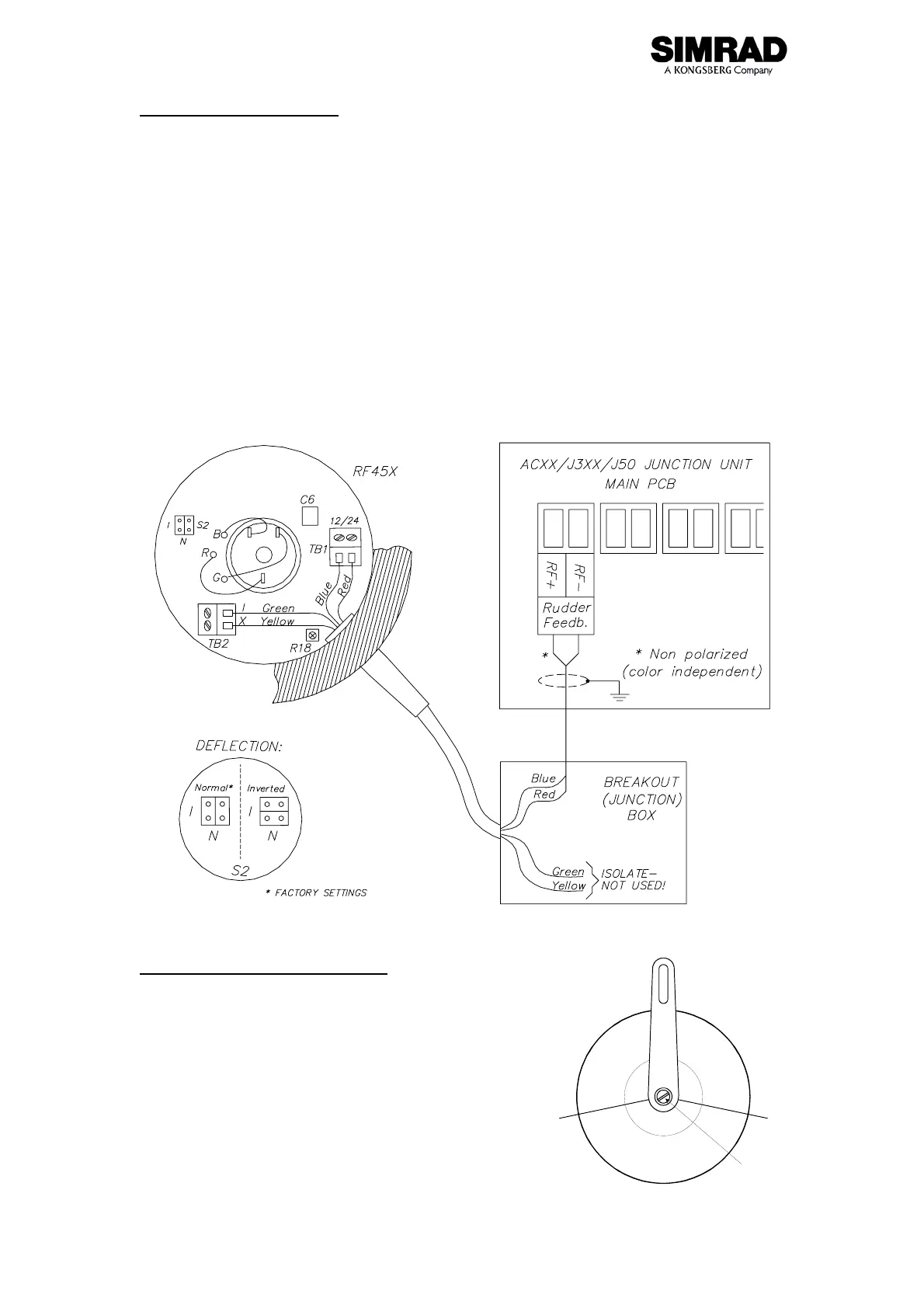
Electrical connection
Use a twisted pair cable AWG20 (0.5 mm
2
) between the breakout box and the
ACXX/J3XX/J50 junction unit. The cable length is not critical but should be kept at a
minimum.
The cable should be connected to the ACXX/J3XX/J50 junction unit according to
Figure 2. When splicing the cables in the breakout box, crimp the enclosed pins on
each wire of the extension cable. Otherwise the wires may be cut off at the terminal
point when the screws are tightened.
The screen is not terminated in RF45X and must be connected in the ACXX/J3XX/J50
junction unit as per instructions in the autopilot manual.
Note!
The green and yellow wire is not used and must be isolated!
Figure 2 ACXX/J3XX/J50 connection
Alignment and calibration
The purpose of this procedure is to make the feedback
unit operate within its active segment. If the unit
operates outside this segment there will be a feedback
failure alarm.
1. Position the rudder amidships.
2. Loosen the two screws that secure the
transmission lever to the RF45X shaft.
F
e
e
d
b
a
c
k
f
a
i
l
u
r
e
z
o
n
e
A
c
t
i
v
e
s
e
g
m
e
n
t
Slot