10
Issue 1.0 16/12/99
3 ASSEMBLYINSTRUCTIONS
3.1General Assembly : WP10
Note :Lubricant is not required, all components should be assembled dry.
Clutch Plate Assembly.Refer to drawing E03047and assemble the clutch plate as
shown ensuring that the M4 Half Nut 200251 locates into the hexagon nut retainer in
the end of the Clutch Roller Shaft and is locked by the application of a small quantity
of Green Loctite 270 - 206625 onto the screw thread prior to assembly. Ensure roller
assemblies both revolve freely.
Rear Plate Assembly. Refer to drawing E03018and fit an M8 Washer 200244 onto
each of the two M8 x 30 Bolts 200243 ensuring that the rounded or smooth side of the
washer faces the head of the bolt and screw the bolts into the Rear Plate E02973 as
shown. When the head of the bolt is within 6mm of the plate apply a small quantity
of Green Loctite 270 - 206625 onto the thread of the screw, under the head, and fully
tighten with an M13 spanner. Assemble the 6 Ring Roller Assemblies and fit to the
Rear Plate securing each Button Headed Screw 200231 with a Nyloc Nut 200259 suf-
ficiently to retain the assemblies but without fully tightening
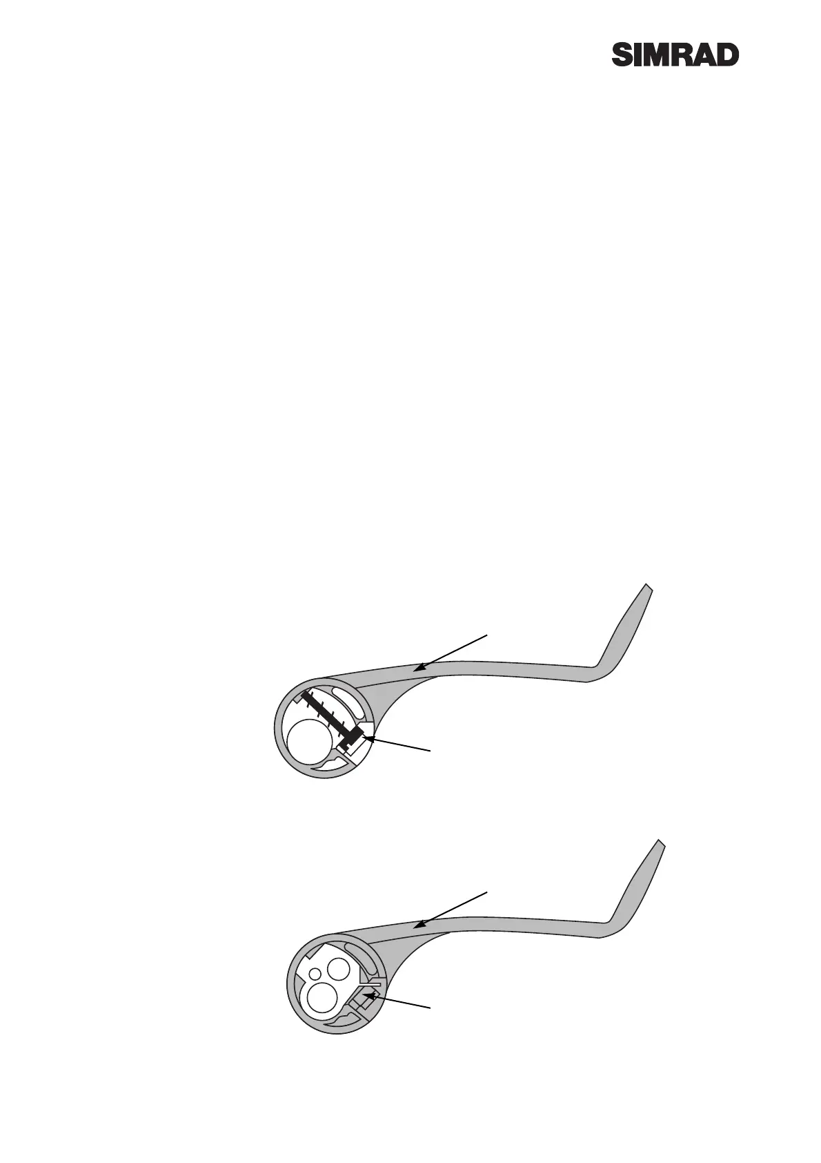
Clutch Handle Assembly. Refer to drawingE03045 and into the boss of the Clutch
Handle E02989 fit Adjusting Screw E03039, ensuring that the slot in the head of the
screw can be seen through the slot in the side of the boss.
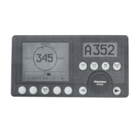
Fit theTension Adjuster E02988.
Clutch
Handle
E02989
Adjusting
Screw
E03039
Clutch
Handle
E02989
Tension
Adjuster
E02988