11
Issue 1.0 16/12/99
Drive Ring Assembly.Refer to drawing No. E03046and fit the 2 Spoke Splines
E02968:BK to the outside of the Front Guide Ring E02967 ensuring that the peg on
the spoke spline locates into the outer hole, in the drive ring. Add a small quantity of
Loctite 270 Green 260025 to the end of the thread of the screw protruding through into
the front drive ring and fully tighten the M4 Half Nut 200147.
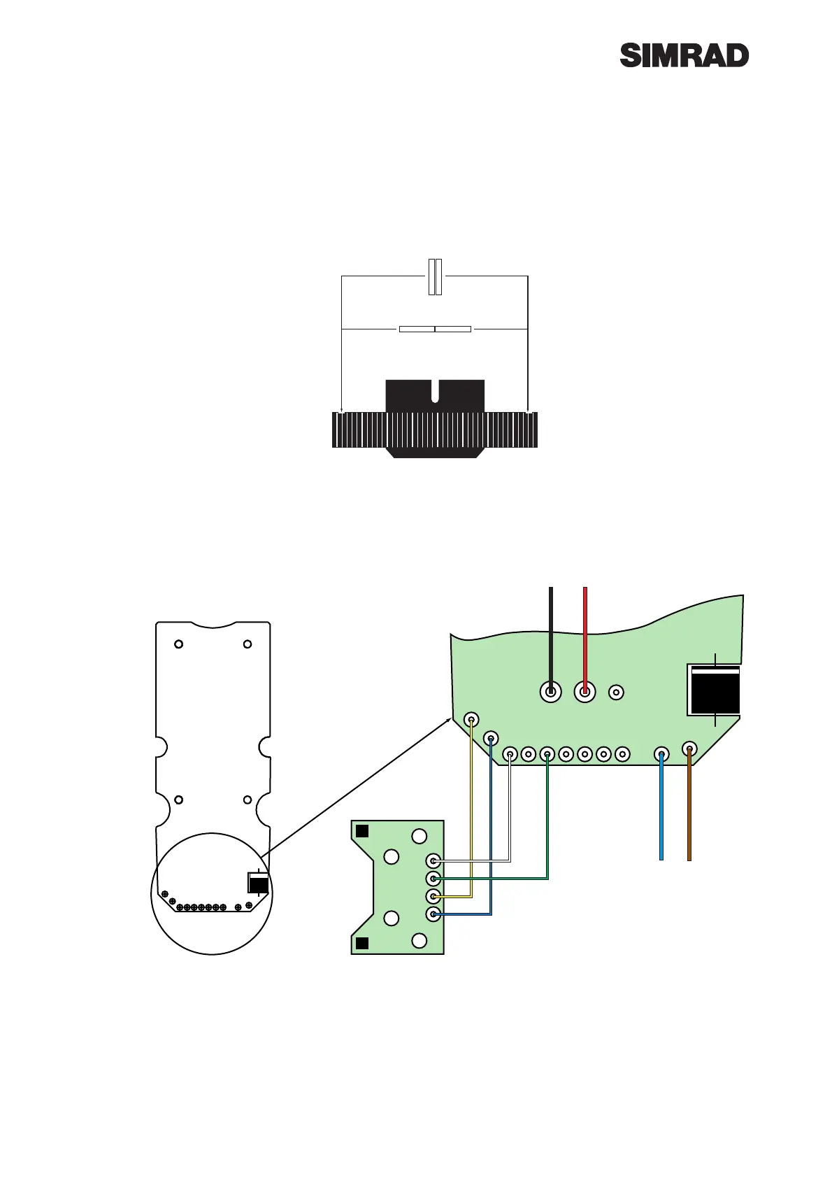
Pulley Magnets Sub-Assembly.Refer to Drawing No E03050and the drawing
below and fit the magnets noting that it is important to maintain the correct polarity.
Wiring to PCB Assembly.Refer to the diagram below, cut to length the eight wires,
prepare them by stripping, twisting and tinning the ends and solder them to the PCB
as shown.
PCB Case Assembly.Refer to drawing No. E03053. Into the case bottom fit a com-
pass and support assembly and secure using 2 off No. 4 X 1/4 screws 200104 and
fully tighten. Connect the compass to the PCB. Fit the Case Seal E02979 into the
groove around the case top and bring the case down onto the top ensuring the seal
is still located correctly. Screw the top to the case using 6off No.4 X1/2” Screws
200002, and fully tighten.
Apply a drop of Loctite 4105
into each hole.
Allow magnets to stick together,
side by side or end to end as
shown.
Separate and fit into pulley as
shown.
MAGNETS
To Drive Motor
BLACK RED
BLUE
0V
BROWN
+V
Hall Effect
PCB
E03184
YELLOW
BLUE
WHITE
GREEN