12
Issue 1.0 16/12/99
Gearbox and PCB Case Assembly.Refer to drawing No. E03086and fit the Ball
Race Seal E03243 onto the Gearbox Assembly E03050. Offer up the gearbox assem-
bly to the Rear Plate E03018 and fit 2 Screws M5 x 10 Csk Pan Poz 200242 through
the rear plate into the gearbox assembly, opposite each other, but do not fully tighten
at this stage. Fit the 2 Screws M5 x 35 Csk Pan Poz 200241 through 2 of the pillars
of the gearbox, add a small amount of Pink 222 Loctite 2600261 to the threads, fit an
M5 half nut onto each and fully tighten all 4 screws.
Refer to Drawing No.E03018and fit a Rubber Grommet 190013 to the Rear Backing
Ring E03018. Peel off the backing paper from the self adhesive side of the Connector
Seal E02985 and stick this to the Rear plate where shown. Apply Hellerman Sleeving
Oil to the Motor Cable of the PCB Case Assembly and guide the cable through the
grommet as the PCB Case Assembly is offered up to the rear plate and pull the cable
through so that the case sits onto the seal. Secure it to the rear plate with 4 Screws
M4 x8 Pan Poz 200210.
Refer to drawing No. E03057and press the cable into the channel on the drive ring.
Refer again to the drawing and push the cable down through the drive ring and the
grommet in the gear box. Pull tight and fit a Tie Wrap 200025 around the cable on the
gearbox side to provide strain relief. Route the wire around the side of the gearbox
and out again through the lower grommet. Apply a bead of Silicone and seal in the
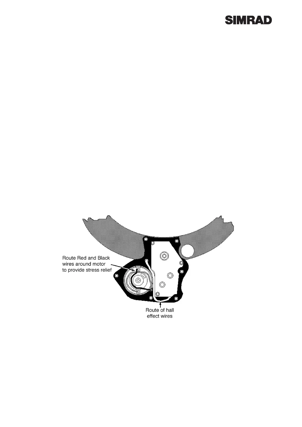
motor cable to the grommet from the PCB Case. Fit a Mu Metal Shield E02992
around the outside of the motor and solder the 2 wires on to the motor ensuring that
the Red wire is soldered to the tag with the Red mark and that the wire is laid around
the motor as shown below to provide strain relief.
When the motor solder joints are made fit a tie wrap around the Mu metal shield and
the Black and Red wires to retain shield and wires.
Hall Effect PCB Wiring and Gearbox Cover Fitting. Refer to drawing No. E03057
and solder the Blue, Yellow, Green and White wires onto the Hall Effect PCB E03184.
Fit the PCB into the Front Gearbox Cover E03043 and screw in using 2 No. 4 x 1/4”
200104. Fit front printed cover onto gearbox and retain with one No. 4 x 5/8 Screw
200067, do not fully tighten. Fit Clutch Handle Assembly E03045 into position on gear-
box drive ring and the Rear Gearbox Cover E02980 and retain with 2 off No. 4 x3/4
Csk Screws 200254 on the inside of the ring. Fit the 4 No. 4 x 5/8 Pan Head Screws
200067 through the gearbox and into the top cover and fully tighten all screws.
 Loading...