13
Issue 1.0 16/12/99
Clutch Plate Assembly. Locate the PTFE Clutch Shim E03040 and, ensuring that it
is orientated correctly onto the cross pin, pass it over the gearbox output shaft so that
it lays flat against the drive ring. Place Clutch Plate Assembly E03047 onto the clutch
shim secure a Clutch Shoe E03041 to the plate assembly through the clutch shim and
gearbox ring and secure with an M4 X 12 Csk Screw 200249, M4 1/2 Nut 200251 and
a small quantity of Green Loctite 270 - 260025. Do not fully tighten at this stage. Fit
the second clutch shoe to the other end of the clutch plate and secure into the Clutch
Handle Assembly previously fitted into gearbox cover and ring. Fit the Pulley Flange
E03036 onto the gearbox output shaft and secure through the shaft with an M3 x 16
Dowel Pin 200234 and then the 16T Pulley E03044 retained by 2 No.4 x 3/8 “ Screws
200079. Tighten the Clutch Shoe screws until operating the clutch handle presents
resistance but still allows the clutch plate to operate smoothly. Fully tighten the
remaining screws.
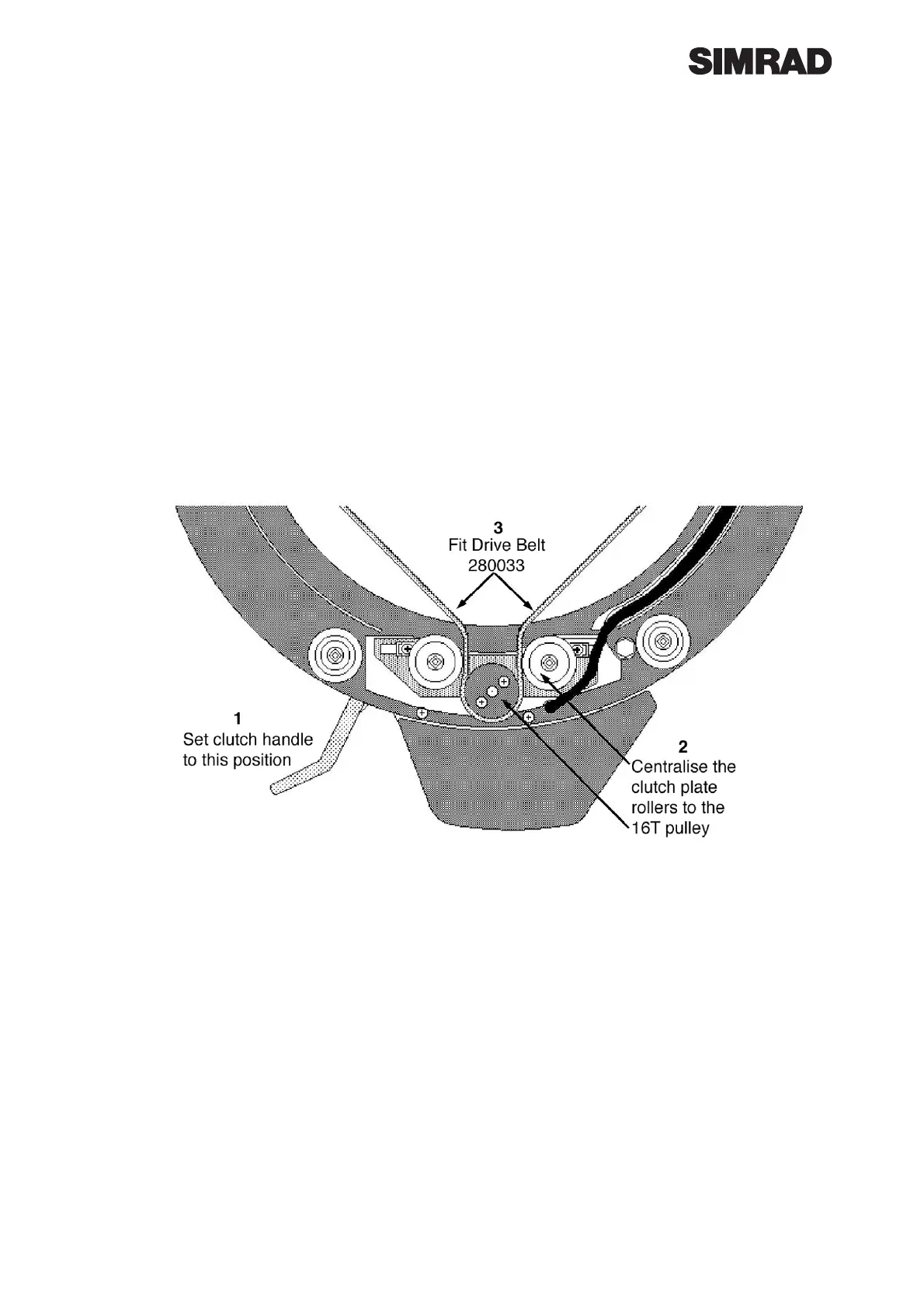
Final Assembly. Refer to the sketch below and set the clutch handle to the midway
position. Position the clutch roller plate so that the two rollers on the plate are equidis-
tant about the 16T drive pulley. Fit belt as shown, and push clutch lever up to capture
the belt. Check all the rollers are loose.
WARNING Care should be exercised in the following operation to avoid trap-
ping fingers.
Place the Drive Ring Assembly (Spinning) over the belt in between the gear box
housing, push the belt up into ring and tuck the six rollers into the drive ring. When all
the rollers are in the ring, turn the unit over and tighten the six mushroom head screws
on the rear.