3.1 Startup and shutdown
64
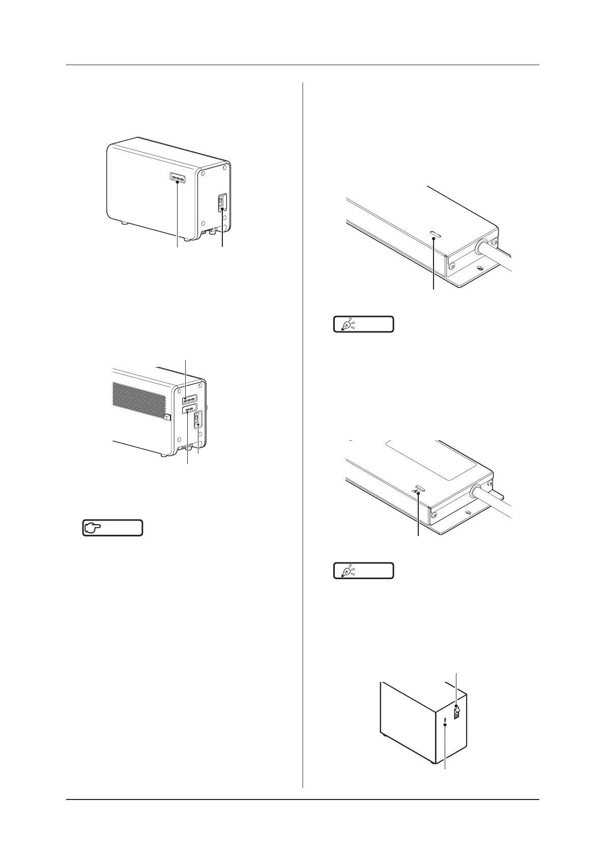
AeroDR Interface Unit
• Turn the power switch of the AeroDR Interface
Unit off, and confirm that the LED (green) is
turned o.
Power switch
LED (green)
AeroDR Interface Unit2
• Turn the power switch of the AeroDR Interface
Unit2 o, and conrm that the Detector Connec-
tion LED (green) and Generator Interface LED
(green) are turned o.
Power switch
Detector Connection LED (green)
Generator Interface LED (green)
Hub
Reference
•••••••••••••••••••••••••••••••••••••
•
When using a general-purpose hub, refer to its operation
manual.
•••••••••••••••••••••••••••••••••••••••••••••••••••••
Detector Interface Unit
• When the Power Supply Unit is turned off,
power supply to the Detector Interface Unit is
terminated. The LED (green) will turn o on the
Detector Interface Unit.
• When using the DI UNIT AC Adapter, remove
the power cable from a wall outlet to turn it o
and the LED (green) will be turned o.
LED (green)
HINT
•••••••••••••••••••••••••••••••••••••
• When DR Detector is connected, the LED (blue) is o.
•••••••••••••••••••••••••••••••••••••••••••••••••••••
Detector Interface Unit 2
• When the Power Supply Unit is turned off,
power supply to the Detector Interface Unit 2 is
terminated. The LED (green) will turn o on the
Detector Interface Unit 2.
LED (green)
HINT
•••••••••••••••••••••••••••••••••••••
• When DR Detector is connected, the LED (blue) is o.
•••••••••••••••••••••••••••••••••••••••••••••••••••••
Power Supply Unit
• Turn the power switch of the Power Supply Unit
o, and conrm that the LED (blue) is turned o.
LED (blue)
Power SW
 Loading...