F
G
H
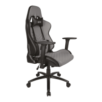
A
I
J
K
L
M
N
O
Q
B
CR
D
E
P
CL
1 2 3
4 5 6
F
E
G
H
REMOVE AND
DISCARD THE
PLASTIC CAP!
I
M
N
B
(FRONT)
(BACK)
I
M
N
C
(FRONT)
(BACK)
J M N
J
M
N
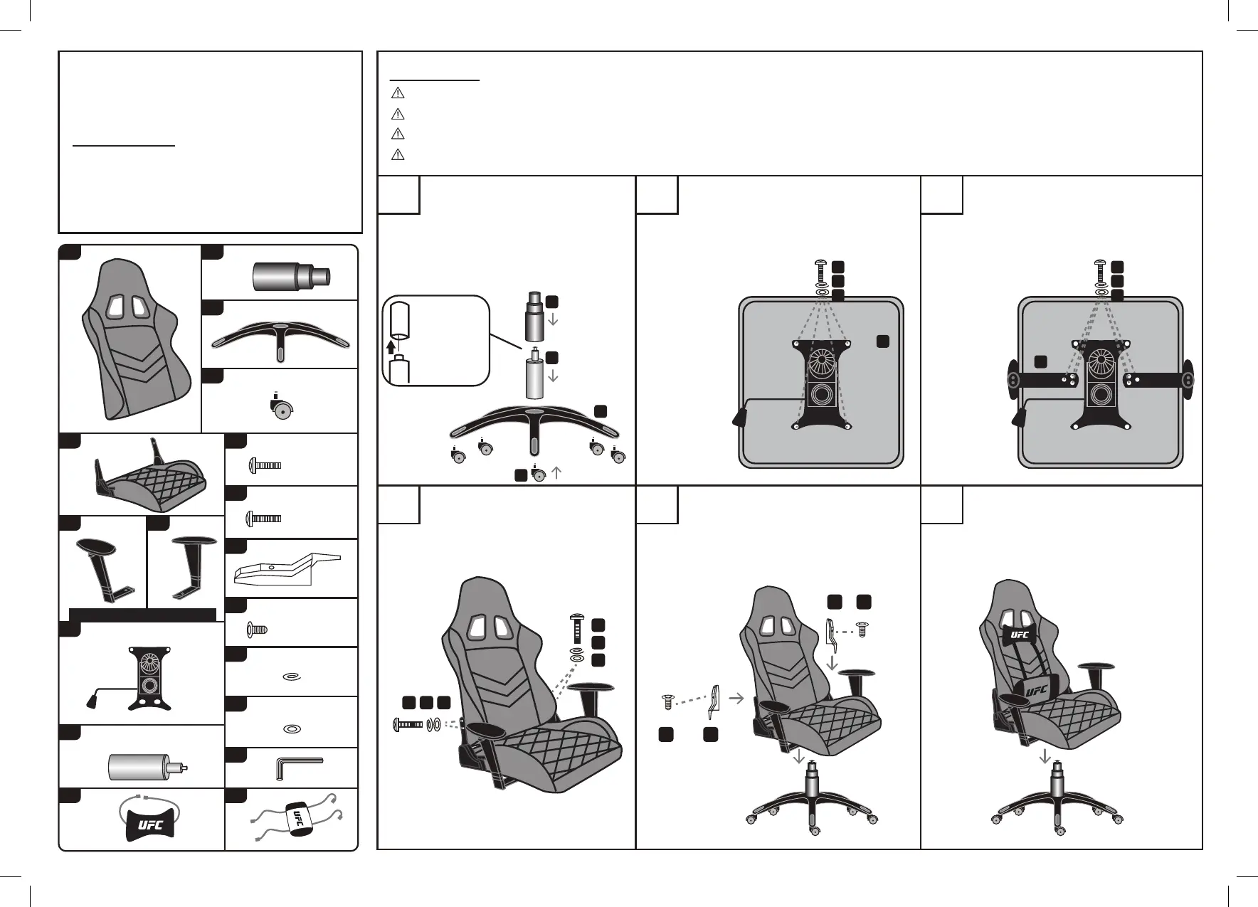
PARTS LIST
ATTENTION: Before you begin the
assembly make sure all parts are
included and in good condition.
x1 Back Rest x1 Plastic covers (Set)
x1Star base
x5 Caster
x10 Screws (Arms, mech.)
x4 Screws (Back rest)
x1 Seat
x1 Mechanism
x1 Hydraulic gas lift
x1 Right arm x1 Left arm
x2 Cover
x14
x14
x2 Screws (Back rest)
M8x25 MM
M8x20 MM
M6x14 MM
ATTENTION:
Follow the instructions step by step.
To avoid misalignments, leave the screws loose and do not tighten them until all are in their respective places.
Do not overtighten or force the screws as they could break, strip, or damage the threads of the holes.
Using the wrong size of screws on a part could result in damage to the screw or the part.
FIRST REMOVE AND DISCARD
THE PLASTIC CAP FROM THE
TOP OF THE GAS CYLINDER (E).
insert the casters (H) into the base (G)
using force. Finally, place the gas lift in
the middle of the base and cover it with (F).
Place the seat (B) with its back towards
you as shown. Using screws (I), and
washers (M) and (N), assemble the
mechanism (D) to the seat with its handle
facing to your LEFT.
With the seat positioned as shown,
assemble the RIGHT armrest (CR) on the
LEFT and the LEFT armrest on the RIGHT
using screws (I) and washers (M) and (N).
Using screws (J) and washers (M)
and (N), assemble the backrest (A) to
the metal brackets on the seat.
Attach the covers (K) to the metal brackets
using screws (L). Then place the top of the
chair over the base making sure the tip of
the gas lift enters in the hole of the
mechanism.
Strap the head pilow (P) at the top, and
the lumbar pillow (Q) at the bottom of the
backrest as shown. Adjust the pillows
according to your needs.
K L
K L
Left/Right is while sitting on chair.
A
 Loading...