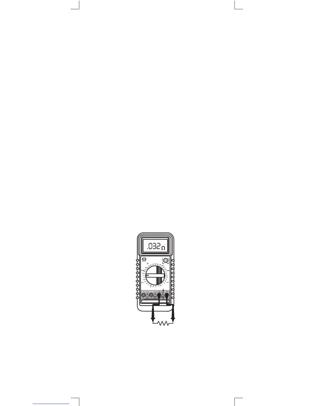
Measuring Resistance Ω
1. Connect the black test lead to the COM jack and the red
test lead to the V/Ω jack. NOTE: The polarity of the red lead
connection is positive (+).
2. Set the function switch at Ω range to be used and connect
test leads across the resistance under measurement.
NOTE:
1. If the resistance being measured exceeds the maximum
value of the range selected or if the input is not connected,
an over range indication (figure “OL” or “1”) will be display-
ed.
2. When checking in-circuit resistance, be sure the circuit
under test has all power removed and that all capacitors
have been fully discharged.
3. When measuring high resistance, the meter reading may
take a few seconds to stabilize. This is normal.
4. For models 292A and 293A at 200MΩ range, the display
reading is around 1 count when test leads are shorted.
This reading should be subtracted from measured results.
For example, when measuring a 100MΩ resistance the
display reading will be 101.0 and the correct measuring
result should be 101.0 - 1.0 = 100.0 MΩ.
20