7. ADJUSTMENT PROCEDURE
7-1
Power supply checK
1 Positive ripple.
Should be no more than 2mVp-p.
Set oscilloscope
vertical
gain at 10mV/cm and
check that power supply ripple is 2mV or less.
2. Negative rippie.
Same
as
positive, should
be no
more than
2mVp*p.
7*2
Pitch adjustment
1. VCO-1.
Perlorm
adjustment with
synthesizer
controls at
"normal setting" {Scale
=0,
Waveiorm^
ru
,
Master
Tune.
Pitch,
arid
all other knobs at
"0").
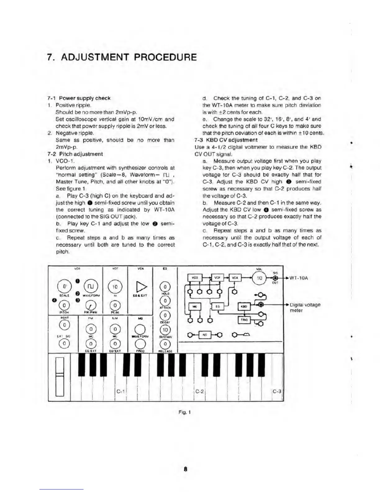
See figure 1
a.
Play C-3 (high C) on the keyboard and
ad-
just the high
0
semi-fixed screw uniM you obtain
the correct tuning as indicated
by
WT-10A
(connected to
tne SiG OUT
jack).
b.
Play key
C<1
and
adjust
the tow
0
semi,
fixed screw.
c.
Repeat steps a and
b
as many times
as
necessary until both are tuned
to
the correct
pitch.
d.
Check the tuning of
C*1. C-2.
and C-3 on
the WT-lOA meter io make sure pitch deviation
iswilh
t2
cents for each.
e. Change the scale to
32',
1S’, $\ and
4'
and
check the tuning of all four C keys to make sure
that the pitch
oeviatlon
of each Is
within tio cents.
7-3 KBD CV adjustment
Use
a
4-1/2
digital voltmeter to measure the KBD
CV
OUT signal.
a. Measure output voltage
first when
you
play
key C-3, then when you play
key
C-2. The output
voltage
icr
c-3 should
be exactly half that for
C-3.
Adjust the KBD CV
high
0
semi -fixed
screw as necessary so that C-2 produces half
the voltage of
C-3.
b. Measure C-2 and then C- 1 1n
the
same way.
Adjust
the KBD CV low
O
eemi-fixed screw as
necessary
so
that
C-2
produces exactly half the
voltage of
C-3
c. Repeat steps a arxf b as many times as
necessary until ouiput vdtage of each of
C-
1 ,
C-2. and C-3 is exactly half ft^al
of
the next.
©'©
©
©
0
MC
0
0
u
0
pH*
•oU
©
0
[>
o
o
mrn
©
©
ATUC«
©
©
VM
©
WT-10A
Digital voltage
meter
C-1 C-2
C-3
\
Ftg. I
s