1,
SPECIFICATIONS
<
CONTROL SECTION
>
1
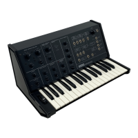
. KeyOoafO
•
F
-^C 32 Keys/(2-2/3
oCBves)
2.
Voltagdccntrolled
•
Scales 132',
16'.
S'.
4M/
ceoilaior
^
S octaves (FM))
•Wave form
(A/s.
PW/PWM.
No4e]/(4
modes)
•
PW adjitsi/PWM imensity
•
Pitch
(1
OCTAVE OR MOREl
• portarnento
•Frecuercy modulation intensity
oy MG
•
Frequency modulation intensity
OyEG/eXT
3. Voltage
controlled eCut'Ott frequency
low pass
Filter
•
Peak Iflat
—
self OSC)
•Cut*oH frequency
rncdulation
intensity
by
MG
•
Oul^off frequency
modulation
intensity by EG/EXT
4. Envelope generator* Hold time
•
Attack time
•
Decay time
•
Sustain level
•
Release time
5. Modufabon
•Waveform r\-
A-
^
in-nj*Lfl
generator
CONTINUALLY
Frequency
6. Extcrnalinput
•
Signal level adjust
7 Manual
controller Control wheel CENTER CLICK
STOP
6- Power. SW A
*Volume
volume
<
PATCH PANEL
SECTION
>
t. Keyboard
2. VCO
3. VCF
4-
VCA
5 EG
6. M3
•Keyboard control
voltage
output
(eirponentiai) 8V
•
Keyboard trigger
output/
•
VCO control voltage Inpul
{linear reepor»se)/OV--
4
8V
•
External frequency
corttrol
input (OCT/V)/
-3V- 43V
•
External pulse width
modulation
input/ -5V-^
4
5V
•
External signal input/3VPf max.
•External
cut-otl frequency con-
trol hput
(2CCT/V)/
-
5V
-
4
5V
•Imtial
gair> control In-
put/0V-45V
•
External trigger Input/
“Loo
•Envelope signal
reverse out-
put/ -5V--
45V
•Triangle output
(f\-A*AD/
5VPP
•
Rectangle output (tn‘rU*Ln)
/0^+6V
7 . Noise
generaiot
•
Pin k noise outp ut/5V PP
•White r^oise
ouipui/5VPP
8. Manual
controller Cor>trol wheel output/
-5V'-0V'-*-5V
9.
Signal out
•Signal ouipui/2VPP max
(output
impodance 3.5kQ)
to.
Powerconsumpiion*5 Watts
•Dimension
•weight
•Acceesonee
•
499(W) X 309(0)
X
249
(
H)
mm
6.3 kgs
•
Patch cord/36 cm x1
2