5 6
9
7 8
10 11 12
14
15 16
13
17
1-2
1 3 42
8
INsTRUCTION
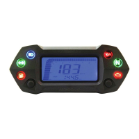
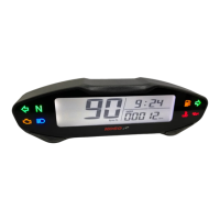
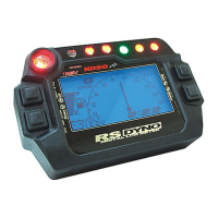
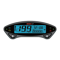
Thank you for purchasing KOSO DB-01 digital LCD meter, before operating the unit, please read the instruction thoroughly and retain it for the
future reference.
Notice
WARNING!
CAUTION!
You could get the installation details from the information behind the mark.
Some processes must be followed to avoid the affection caused by wrong installation.
Some processes must be followed to avoid damages to yourself or the public.
Some processes must be followed to avoid the damage to the vehicle.
MARK MEANING:
1.The meter is apply for DC 12V.
2.For installation, please follow the steps described in manual. Any damage caused by wrong installation shall be imputed to the users.
3.To avoid the short circuit, please don't pull the wire when installing. Don't break or modify the wire terminal.
4.Do not disassemble or change any parts excluding the manual description.
5.The interior examination or maintenance should be executed by our professionals.
Accessory
1-1
PRESS THE
BUTTON ONE TIME
PRESS THE
BUTTON 3
SECONDS
Mid-way connect X 8
D6 X 5L mm magnet X 6
Passive speed sensor X 1
M8/ S type speed
sensor bracket X 1
M10/ S type speed
sensor bracket X 1
Hexagon socket
screw X 2
2.5 mm spanner X 1 4 mm spanner X 1
Manual
Please contact the local distributor if the items you open are not the same, with the above-listed one.
6
JIS TYPE a
SR
X-FIGHT
BOOSTER
Option accessory
Digital speed signal
sensor
RUNNER
Digital speed signal
sensor
Digital speed signal
sensor
Active speed sensor
Disc magnet screw
1 32
5/16-18 X 22.1L
M5 X P0.8 X 12L
M6 X P1.0 X 12.6L
M6 X P1.0 X 19.7L
M6 X P1.0 X 24L
M8 X P1.25 X 22.5L M8 X P1.25 X 27.5L
M8 X P1.25 X 29L M10 X P1.25 X 28.3L
5
L type speed sensor
bracket
7
JIS TYPE A
Digital speed signal
sensor
4
2-1
2-2
Some of the option accessories may not sell. For the details, please contact the local distributor.
The advantage of the active speed sensor is as following, 1. You don't need to install the magnet in the opposite position of the speed
sensor. 2. You could set up the sensor signal input up to 60 points, and the speed displayed will be more accurate. Please note that the
speed sensor attached in the kit is passive speed sensor, and the maximum speed signal it could read is 6 points.
Meter bracket
(for handle switch)
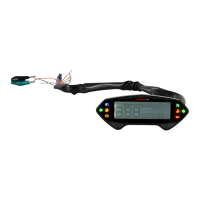
Main wiring X 1
Meter X 1
M4 gasket X 2
M5 X 12L screw X 2 M4 screw X 2
Wiring installation instructions
Installation instructions
When installing, please follow the process.
RPM wire set (Type A) X 1 RPM wire set (Type B) X 1
Meter bracket X 1 set
E
F
Flywheel
EMS
CDI
pick up
Ignition
pulse
Spark plug wire
Spark
Coil
RPM wire set-type A
(Accessory 3)
AA1A3
C
B1B A2
D
Tachometer
RPM wire set-type A
(Accessory 3)
RPM wire set-type B
(Accessory 4)
YAMAHA
HONDA
SUZUKI
KAWASAKI
SYM
KYMCO
PGO
Main switch wiring reference:
Power
Ground
Brown
Brown
Black
Green
The color listed above may differ depending
on the model.
Black
Black
Black
Black
Green
Green
Key on
Red
Red
Red
Red
Red
Red / White
Orange
Green
Red / Black
White
Black / Yellow
Yellow / Green
YAMAHA
HONDA
SUZUKI
KAWASAKI
BMW
BENNELLI
APRILIA
Light Blue
Yellow / Blue
Yellow / Black
Black
Gray / Violet
Gray / Violet
DUCATI
BUELL
CAGIVA
H-D
MV
Gray / Green
Gray / Green
Gray / Yellow
Pink
Pink
RedTRIUMPH
RPM wiring reference:
The color listed above may differ depending
on the model.
When connecting the power wiring, please follow the instruction. If you connect the red & brown wiring in parallel will cause the meter work improperly.
The temperature will disappear if you don't install & connect the temperature sensor with the meter.
The RPM wire installation
A. Please wrap the RPM wire at least 5 times around the spark plug.
A1. Please use tape to fix the RPM (Type A) wire onto the spark plug wire.
A2. Please use tape to fix the RPM wire (Type A) on the spark plug cap.
A3. Please use tape to fix the RPM wire (Type A) on the coil positive pole wire. For some models with the coil negative wire, please tape
the RPM wire (Type A) on the negative wire to get the RPM signal. (For example, the YAMAHA V-max 1200)
B. Please connect the RPM wire (type B) to connect to the ignition coil positive pole.
B1. Please wrap the RPM wire (type B) on the spark plug wire by connecting the male and female connector.
C. Please connect the RPM wire (Type A) to the pick up.
D. Please parallel the RPM wire (Type A) with the original tachometer signal wire (This method is available only when the original
speedometer comes with a tachometer on it. You could get the RPM wire information from the service manual of your bikes.)
E. For the models comes with the new ignition coil, please wrap the RPM wire (Type A) at least 5 times around the spark plug as the
above drawing.
F. Please use the method mentioned above to install the RPM wire, and then connect the ground wire to the frame body or the
engine. (Please make sure that the ground is a good ground.)
For multi-ignition models, we will suggest you to get the signal on the first ignition.
The best signal source will be in order as D>C>B>A, we will suggest you to check different ways if you have problems to get the
RPM signal.
YAMAHA
SUZUKI
HONDA
Yellow / White
Yellow / White
The fuel sensor is electronic type, please don't
parallel connection with the original- otherwise
the fuel gauge won't display.
The wrong installation of the fuel wiring may
cause the meter break.
Green
Fuel indicator wiring reference:
KAWASAKI
SYM
KYMCO
PGO
Black / L Green
Gray
Yellow / White
Yellow / White
RPM wire set
Ground
Ignition coil positive
Spark plug
cap
Main wiring (Accessory 2)
Meter (Accessory 1)
Active speed sensor (Accessory 7)
Brown/ RPM wire please connect it to the
suitable position according to the models.
Black / Ground wire connect to the vehicle
body or the engine (It must be a good ground)
Red / "+"Wire connect key on
DC 12V main power switch
Orange / L turn signal (+12V)
Green / fuel (-)
Yellow / High beam light (+12V / -1.8V)
Blue / R turn signal (+12V)
Gray / OIL light (+12V / -)
White / Neutral light (+12V / -)
Magnet (Accessory 8)
1. M5 X 12L screw X 2
2. Meter bracket for handle bar
3. Fix the bracket on handle bar (7/8 inch)
4. Meter bracket clip X 1
5. M4 screw X 2
6. M4 gasket X 2
7. Meter fixed board
8. Fix the meter on the board (7) with the gasket (6) screw (5)
9. Fix the meter and the bracket together
10. Pull the meter bracket clip upward to fix the bracket.
Please adjust the meter to the best visible angle before
tightening the screw
wh018ba000-1
1.
2.
3.
2.
4.
5.
7.
8.
6.