EasyManua.ls Logo

Koso TNT-B User Manual

Koso TNT-B
6 pages
To Next Page IconTo Next Page
Page #1 background imageLoading...
Page #1 background image
Installation description
2-1
Please proceed as follows
NOTE
Please refer to the icon to disassemble. And install according to
the reverse order of disassembly.
Bracket Bushing (Accessories 2)
Collar (Accessories 3)
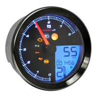
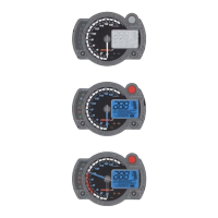
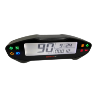
LCD Meter (Accessories 1)
M5nut(Accessories 5)
M5 washer(Accessories 4)
Accessories
1
1 2 3
5
M5 nut X3
4
M5 washer X3Collar X1
Bracket Bushing X2
LCD Meter X1
NOTE
Contact your local distributor, if the items received in the box are not the same as the items listed above.
Thank you for purchasing the TNT-B meter for Yamaha Bolt
®
. Before installing, please read the instruction carefully and keep it for future reference.
For installation, please follow the steps described in manual. Any damage caused by wrong installation shall be imputed to the users.
Don't break or modify the wire. To avoid the short circuit, please don't pull the wire when installing.
Do not disassemble or change any parts excluding the manual description.
The interior examination or maintenance should be executed by our professionals.
 
Attention!
MARK MEANING:
Some processes must be followed to avoid the damage to the vehicle.
Some processes must be followed to avoid the affection caused by wrong installation.
Some processes must be followed to avoid damages to yourself or the public.
WARNING!
CAUTION!
NOTE
You could get the installation details from the information behind the mark.
PRESS THE
BUTTON
ONCE
PRESS THE
BUTTON 3
SECONDS
FLASH LIGHT ON

Questions and Answers:

Koso TNT-B Specifications

General IconGeneral
BrandKoso
ModelTNT-B
CategoryMeasuring Instruments
LanguageEnglish

Summary

Accessories List

Installation and Wiring Guide

Installation Steps (Part 1)

Details initial assembly steps for bracket bushings, collars, and the LCD meter.

Installation Steps (Part 2)

Continues assembly with washers and nuts for the meter installation.

Wiring Connection Instructions

Provides guidance on connecting the meter's wiring harness to the vehicle's main wire.

Wire Installation Precautions

Outlines critical precautions for securing and protecting wire connections during installation.

Functionality and Settings Overview

Basic Function Display Details

Explains display ranges and units for tachometer, odometer, fuel level, and speedometer.

Setting Parameters Explained

Details setting parameters for speedometer, thermometer, oil maintenance, and tire percentage.

Main Menu Navigation

Describes how to navigate the meter's main menu and access different display modes.

Setting Screen Operations

Navigating Setting Screens

Guides users through operating various setting screens on the meter.

Advanced Calibration: Tires and Gears

Tire Percentage Calibration

Adjust tire percentage for accurate speed calibration after tire changes.

Gear Indicator Learning

Details the procedure for learning and setting up the gear indicator display.

Troubleshooting Common Issues

Related product manuals