EasyManua.ls Logo

Koso GP - User Manual

Koso GP
6 pages
Print Icon
To Next Page IconTo Next Page
Loading...
wh642bb03b-P4-1
Brown & Red / RPM wire
RPM wire set (Type B)
(Accessory 5)
Ignition coil positive
Flywheel
Tachometer pick up
Coil Spark plug wire
Spark plug
cap
Spark
RPM wire set (Type A)
(Accessory 4)
RPM wire set (Type A)
(Accessory 4)
Magnet (Accessory 3)
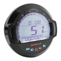
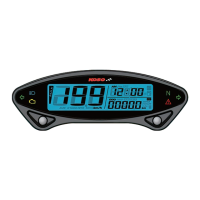
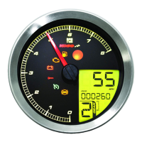
Thank you for purchasing KOSO style speedometer. Before operating the unit, please read the instruction thoroughly and retain it for the future
reference.
Red (+12V) (Connect to the battery DC 12V )
Orange / L turn signal (+12V)
Purple / EOBD light (-)
NOTICE
1.The lcd meter is apply for DC 12V .
2.For installation, please follow the steps described in manual. Any damage caused by wrong installation shall be imputed to the users.
3.To avoid the short circuit, please don't pull the wire when installing. Don't break or modify the wire terminal.
4.Do not disassemble or change any parts excluding the manual description.
5.The interior examination or maintenance should be executed by our professionals.
MARK MEANING:
NOTE
You could get the installation details from the information behind the mark.
Some processes must be followed to avoid the affection caused by wrong installation.
WARNING!
CAUTION!
Some processes must be followed to avoid damages to yourself or the public.
Some processes must be followed to avoid the damage to the vehicle.
Flash Press the
button
one time
Press down the
button
for 3 seconds.
ACCESSORY
OPTION ACCESSORY
Meter X1
Passive speed sensor (Accessory 2)
D6 x 5L mm magnet x 6 RPM wire set (Type A) X1Passive speed sensor X1
Mid-way connect X 11
2.5 mm allen key x 1
Rubber x 1
M5 washer x 2
Bolt Magnet
M6 washer x 1
Active speed sensor
L type speed sensor
bracket
Aluminum bushing x 1
M6 x 18L mm screw x 1 M5 x P0.8 mm nut x 2
V type Meter bracket x 1
set
M8/ S type speed
sensor bracket x 1
M10/ S type speed
sensor bracket x 1
NOTE
Please contact the local distributor if the items you open are not the same, with the above-listed one.
NOTE
The color listed above may differ depending
on the model.
The fuel sensor is electronic type, please don’t
parallel connection with the original- otherwise
the fuel gauge won’t display.
The wrong installation of the fuel wiring may
cause the meter break.
NOTE
Some of the optional accessories listed might not be sold in your country. Contact your local distributor to get more details.
NOTE
The optional active speed sensor can read up to 20 pulsations and not require the installation of any magnets to pick up the speed.
Note that the passive speed sensor supplied with this instrument can read up to 6 pulsations.
WIRING INSTALLATION INSTRUCTIONS
INSTALLATION INSTRUCTION
FOLLOW THOSE STEPS WHEN INSTALLING
Blue / R turn signal (+12V)
Yellow / High beam light (+12V)
Gray / Oil light (-)
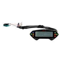
Speed sensor wiring
Yellow & White / State of
Charge (DC 12V) Black / Ground wire connect to the
vehicle body or the engine (it must
be a good ground)
Brown / “+” Wire connect
key on DC 12V main
power switch
Green / Fuel
White / Neutral light (-)
Meter (Accessory 1)
Main switch wiring reference:
Fuel indicator wiring reference:
Red
Green
Yellow / White
Yellow / White
Black / L Green
Yellow / White
Yellow / White
Gray
Red
Red
Red
Red
Red / White
White
Brown
Red / Black
Black
Black
Black
Orange
Brown
Black
Green
Green
Green
Green
Black
Black / Yellow
Power Ground
1. LCD meter (Accessory 1)
2. Meter bracket (Accessory 11)
3. M5 washer x 2 (Accessory 17)
4. M5 x P0.8 nut x 2 (Accessory 15)
5. M6 x 18L screw (Accessory 14)
6. M6 washer (Accessory 18)
Use the meter bracket (Accessory 11), handle bar clamp
(Accessory 12), rubber (Accessory 13) and M6 x P1.0 nut (Accessory 16)
to install the speedometer on the handle bar.
Use the aluminum bushings (Accessory 11) to install the speedometer on
the handle bar stem.
Handle bar clamp x 1
M6 x P1.0 mm nut x 1
RPM wire set (Type B) X1
M5 x 5L mm Hexagon
screw x 2
NOTE
The RPM wire installation
A.Please wrap the RPM wire at least 5 times around the spark plug.
A1. Please use tape to fix the RPM (Type A) wire onto the spark plug wire.
A2. Please use tape to fix the RPM wire (Type A) on the spark plug cap.
A3. Please use tape to fix the RPM wire (Type A) on the coil positive pole wire. For some models with the coil negative wire, please tape
the RPM wire (Type A) on the negative wire to get the RPM signal. (For example, the YAMAHA V-max 1200)
B.Please connect the RPM wire (type B) to connect to the ignition coil positive pole.
B1. Please wrap the RPM wire (type B) on the spark plug wire by connecting the male and female connector.
C.Please connect the RPM wire (Type A) to the pick up.
D.Please parallel the RPM wire (Type A) with the original tachometer signal wire (This method is available only when the original
speedometer comes with a tachometer on it. You could get the RPM wire information from the service manual of your bikes.)
E.For the models comes with the new ignition coil, please wrap the RPM wire (Type A) at least 5 times around the spark plug as the
above drawing.
F.Please use the method mentioned above to install the RPM wire, and then connect the ground wire to the frame body or the engine. (Please make sure
that the ground is a good ground.)
For multi-ignition models, we will suggest you to get the signal on the first ignition.
The best signal source will be in order as D>C>B>A, we will suggest you to check different ways if you have problems to get the
RPM signal.
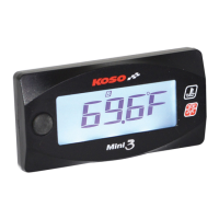
The temperature will disappear if you don't install & connect the temperature sensor with the meter.
When connecting the power wiring, please follow the instruction. If you connect the red & brown wiring in parallel will cause the meter work improperly.
Question and Answer IconNeed help?

Do you have a question about the Koso GP and is the answer not in the manual?

Summary

Setting Screen Instructions

RPM Input Signal Setting

Configure the RPM input signal based on flywheel signals per turn.

Tire Circumference Compensation

Adjust tire circumference setting for accurate speed display.

Sensor Point Setting

Set the sensor point value for optimal speed detection.

Fuel Resistance Setting

Set the fuel gauge resistance for accurate fuel level display.

Clock Setting

Set the current time for the speedometer display.

Backlight Brightness Setting

Adjust the display backlight brightness level.

Internal Odometer Display

View or set the internal odometer reading.

External Odometer Setting

Set the external odometer value, typically for data transfer.

Troubleshooting Guide

Meter Not Working

Check power supply, wiring, and fuse if the meter is unresponsive.

Incorrect Information Display

Verify settings and connections for display accuracy.

Speedometer Issues

Check tire-size setting and sensor alignment for speed errors.

Fuel Gauge Issues

Verify fuel level, wiring, and fuel resistance settings.

Odometer;Trip Meter Data Errors

Ensure the permanent power wire is correctly connected.

Overview

This document describes the KOSO GP style speedometer, a DC 12V compatible meter designed for motorcycles. It provides detailed instructions for installation, operation, and troubleshooting.

Function Description

The KOSO GP style speedometer offers a comprehensive suite of functions for monitoring vehicle performance and status. Key functions include:

  • Speedometer: Displays current speed in a range of 0-360 km/h (0-225 MPH) with a display unit of 1 km/h (MPH) and a display interval of less than 0.5 seconds.
  • Odometer: Tracks total distance traveled from 0 to 99999.9 km (mile), automatically resetting after 99999.9 km (mile). The display unit is 0.1 km (mile).
  • Trip Meter A & B: Records short-distance trips from 0 to 999.9 km (mile), automatically resetting after 999.9 km (mile). The display unit is 0.1 km (mile).
  • Fuel Level: Indicates fuel level with 4 display levels. The fuel level symbol flashes when only 1 level of fuel remains. If the fuel wiring is not installed, this function will not display.
  • Fuel / Remaining Distance: Estimates remaining distance from 999.9 to 0 km (mile) with a display unit of 0.1 km (mile). This function requires a learning procedure after filling the tank.
  • Tachometer: Displays engine RPM with 15 levels, where each level represents 1000 RPM.
  • Clock: Shows time in a 24-hour format.
  • Digital Volt Meter: Displays battery voltage in a range of DC 5-24 V. It flashes a warning when voltage is lower than 8V or higher than 18V.
  • Volt Meter: Indicates battery voltage with 4 levels. The voltage level symbol flashes when only 1 level remains.
  • Indicator Lights: Includes lights for Turn Signal (Green), Neutral (Green), High Beam (Blue), Engine Oil Pressure (Red), and EOBD (Amber).
  • Backlight Brightness Adjust: Allows adjustment of backlight brightness with 5 levels (Darkest to Brightest), each adjustment adding 20% (5 segments).

Important Technical Specifications

  • Operating Voltage: DC 12V
  • Effective Temperature Range: -10 to +60°C
  • Meter Standard: JIS D 0203 S2
  • Meter Size: 135.7 x 100.7 x 52 mm
  • Meter Weight: Around 240g
  • Tire Circumference Setting Range: 300-2500 mm (setting unit: 1 mm, sensor point: 1-20)
  • Fuel Resistance Setting Range: 1000, 2500, 5100, 12000
  • RPM Input Signal Setting Range: 0.5, 1-24 (RPM per spark)
  • Backlight Brightness Setting: 1-5 (Darkest to Brightest), 20% per level.

Usage Features

The speedometer is designed for intuitive use with two main buttons: "Select" and "Adjust."

  • Main Screen Navigation:
    • Press "Select" to switch between clock, volt.
    • Press "Adjust" to switch between Odometer, Trip A, Trip B, Fuel / Remaining Distance.
    • Hold "Select" for 3 seconds to switch between fuel, volt, RPM.
    • Hold "Select" for 3 seconds in RPM screen to switch back to fuel, volt screen.
    • Hold "Adjust" for 3 seconds in ODO screen to switch between digital speedometer and digital odometer.
  • Setting Screen Access: Hold "Adjust" + "Select" for 3 seconds from the main screen to enter the setting screen.
  • Setting Value Adjustment:
    • In setting screens, press "Select" to change the setting cursor.
    • Press "Adjust" to change the setting value.
    • Hold "Adjust" to change setting values faster.
  • Reset Functions:
    • Hold "Adjust" for 3 seconds in Trip A or Trip B screen to reset the trip record.
    • Hold "Adjust" for 10 seconds in Fuel / Remaining Distance screen to reset remaining mileage to 0 and restart learning.
  • Standby Function: When the meter is off, pressing "Adjust" or "Select" button wakes up the clock function for 30 seconds.
  • RPM Input Signal Setting: Allows configuration of RPM signal input based on engine type (2-stroke/4-stroke) and number of pistons, or by connecting to the pick-up signal. The setting range is 0.5 to 24.
  • Tire Circumference Compensation Setting: Enables adjustment of the tire circumference (300-2500 mm) to ensure accurate speed readings, especially when changing tire sizes.
  • Fuel Resistance Setting: Configures the fuel gauge to match the resistance of the vehicle's fuel sensor (1000, 2500, 5100, 12000).
  • Clock Setting: Sets the time in 24-hour format.
  • Internal/External Odometer Setting: Allows setting of internal and external odometer values.

Maintenance Features

The manual provides a troubleshooting guide for common issues:

  • Meter not working when power is on: Check power supply to the meter, wiring connections, and fuse. Verify battery condition and voltage (must be over DC 12V).
  • Meter shows wrong information: Check battery voltage.
  • Speed not appearing or appearing incorrectly: Verify speed sensor cable connection, check tire-size setting (refer to manual 4-2).
  • Fuel gauge not appearing or appearing incorrectly: Check fuel tank level, fuel wiring connections, and fuel resistance setting (refer to manual 4-3).
  • Odometer and trip meter not accumulating or accumulating wrong data: Check if the permanent power wire (red positive wire) is connected correctly.

For any issues not resolved by the troubleshooting steps, users are advised to contact distributors. The manual also emphasizes the importance of professional examination and maintenance for internal components. Users are warned against disassembling or changing parts not described in the manual.

Koso GP Specifications

General IconGeneral
BrandKoso
ModelGP
CategoryMeasuring Instruments
LanguageEnglish

Related product manuals